The information in this article applies to:

QUESTION
I would like to create a structurally detailed pole barn type building in my legacy program version (X12 and prior). How can I do this?

ANSWER
In Chief Architect legacy versions (X12 and prior), the program's framing and CAD tools will need to be used creatively to design a pole barn structure, as automatic functionality to create such components did not exist.
If you're using a newer Chief Architect version, please refer to KB-03137: Designing a Structure Using Post-Frame Construction.
There are a number of distinct tasks involved in this project:
Before starting work on any drawing, it is important to set up the correct default settings, particularly for the structural aspects of the plan.
To prepare to draw the structure
- Select Edit> Default Settings
 from the menu to open the Default Settings dialog.
- To expand a category in the tree list and view its subcategories, click the arrow to the left of its name.
- To open the defaults dialog for a line item, click on its name and then click the Edit button, or simply double-click on its name.
- Some defaults - notably, Dimensions - have multiple Saved Defaults. Each Saved Default's name is included in the name of its defaults dialog, and will be noted in the steps that follow.
- In the 1/4" Scale Dimension Defaults dialog, on the Locate Objects panel:
- Click the radio button beside Wall Dimension Layer.
- Click the radio button beside Primary Wall Side.
- Check the box beside Rough Opening.
- In the Auto Exterior Dimension Defaults dialog, on the Locate Objects panel:
- Click the radio button beside Wall Dimension Layer.
- Click the radio button beside Primary Wall Side.
- Check the box beside Rough Opening.
- In the Exterior Door Defaults dialog, specify the type of exterior man-door that you would like.
In this example, the E11 door from the Library is used.
- In the Garage Door Defaults dialog, specify the type of garage door that you would like.
- In this example, the Garage Door CHD09 from the Library Browser is used.
- The Door Height is set at 10' and the Door Width, at 12'.
- On the Framing panel, specify all Rough Opening values as 0".
- In the 1st Floor Defaults dialog:
- On the Structure panel, specify the desired Rough Ceiling height, which determines the wall's top plate height and also the height of the roof trusses' bottom chords. In this example, 12' is used.
- Also on the Structure panel, check the box beside Monolithic Slab Foundation.
- On the Moldings panel, use the Delete button to remove the Molding profiles assigned to this floor.
- On the Foundation panel of the Foundation Defaults dialog:
- Click the radio button beside Monolithic Slab.
- Specify the desired Slab Thickness. In this example, 4" is used.
- Click the Edit Default Slab Footing button and specify the desired Footing size. In this example, the default 16" x 8" footing is used.
- In the Framing Defaults dialog:
- On the Beams panel, click Edit Roof Beam Defaults. In this example, the Depth is set to 11 7/8", the Width is 3 1/2" and the Type is LVL. This is the equivalent of two 1 3/4" LVL members laminated together.
- On the Posts panel, click Edit Post Defaults to specify the desired Post Size. In this example, both widths are set to 7 1/2" and the Type is Lumber.
- Also on the Posts panel, specify the Post Footings. In this example the Thickness is 48", the Width is 24" and the radio button beside Round is selected.
- On the Roof panel, do not make any specifications at this time. We will discuss Roof defaults when we actually build the roof.
- On the Trusses panel, specify the desired Member Depth values. In this example, the Top Chord, Bottom Chord and Webbing are set at 5 1/2" and Require Kingpost is checked.
- In the Exterior Wall Defaults dialog:
- On the Wall Types panel click the Define button to open the Wall Type Definitions dialog. Create a new custom wall type with three layers for our default exterior walls. Give the new wall type a short, descriptive name such as "Pole Structure - 8".
- Layer 1 is the exterior siding. Specify the desired Material and Thickness. In this example, 3/4" of Slate Corrugated Metal roofing is used.
- Layer 2 will be for the girts. Set the Thickness as 1 1/2" and the Material as "Opening (no material)". Specify Layer 2 as the Main Layer so that trusses can be placed above that layer.
- Layer 3 is for the posts. The Material should be "Opening (no material)". The Thickness will be equal to the default Dimensions of our posts - in this example, 7 1/2".
- In the Wall Settings section, set Foundation to Exterior of Layer to layer 3.
- Because the structure will be manually framed, consider specifying a pale Fill color or even solid white for the framed layers so the framing members can be easily seen.
- When finished setting defaults, click the Done button at the bottom of Default Settings dialog.
- Select Build> Roof> Build Roof
 from the menu. On the Roof panel of the Build Roof dialog:
- Specify the desired Pitch. In this example, 6:12 is used.
- Check the box beside Trusses (no Birdsmouth).
- Specify the desired Roof Overhang values. In this example, the Eave Overhang is 18" and the Gable Overhang is 2 1/2".
- Uncheck Automatic Birdsmouth Cut and set the Raise Off Plate value to 8".
- Confirm that the Working Layer Set and 1/4" Scale Default Set are set in your Active Defaults
 .
.
If you plan to design pole structures in the future, now is a great time to save your default settings for use as a template plan.
To create a pole structure template plan, select File> Templates> Save As Template  from the menu. Give the file a short, descriptive name such as "Pole Structure Template", and save it in the Chief Architect Templates directory, or the location of your choice.
The program will ask if you want to make your new template your default template for new plans. Unless you expect that most of your new projects will be pole structures, click No.
Once the defaults are set up, the structure can be drawn.
To draw the perimeter walls and place doors
- Select Build> Wall> Straight Exterior Wall
 , then click and drag to draw shape of the perimeter.
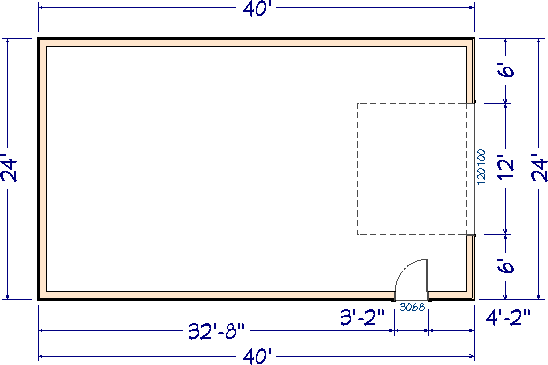
In this example, a simple 24' x 40' rectangular structure is used. Dimensions were previously set to locate the girts wall layer.
- Click in the room to select it, then click the Open Object
 edit button. In the Room Specification dialog:
- On the General panel, select Slab from the Room Type drop-down list.
- On the Structure panel, uncheck Flat Ceiling Over This Room.
- Select Build> Door> Hinged Door
 from the menu, then click on a wall to place a door. Starting in X11, barn doors can be added without using a library object by going to Build> Door> Barn Door
  .
.
Click on the door near the exterior edge, then use the Temporary Dimension to position it the desired distance from the corner.
In this example, a 3068 door is placed 4' 2" from the lower right interior corner.
- Select Build> Door> Garage Door
 from the menu, then click on the left wall to place a garage door at that location.
With the garage door still selected, click the Center Object  edit button, then click inside the room to center the door along the wall.
To place the posts and add the slab
-
Zoom
 in on one of the corners on the right side of the structure, select Build> Framing> Post with Footing
  and click to place a post with a footing close to the intersection of the two walls.
- Hold Shift and click both the post and footing as a group selection, then use the Point to Point Move
 edit tool to position the post precisely in the corner of the 7 1/2" main wall layer.
This is easiest if Object Snaps  are enabled - particularly Endpoint Snaps
  .
.
- With only the post selected, click the Open Object
 edit button. On the General panel of the Framing Specification (Post) dialog:
- Remove the check-mark from Raise/Lower.
- Click the radio button to Lock the Total Height, then specify the desired Top Height. In this example, the Top Height is 13' 2" (or 158"), which is 14" above the bottom chord of the roof trusses.
-
Lock the Top, then specify the desired Bottom Height. In this example, the Bottom Height is set at -48" so that it extends from the top of the floor, through the 4" slab and 44" into the footing.
- On the Line Style panel of the Framing Specification (Post) dialog box verify that the Layer is set to Framing, Posts.
- On the Fill Style panel of the Framing Specification (Post) dialog, Select Solid from the Fill Pattern drop-down list and set the Color to White.
- On the Materials panel you can create a green treated lumber material for the poles. In this example, we copied the material, CA-B Pressure Treated Lumber, and blended a green color with it.
- With the Select Objects
 tool, click on the footing to select it, then click the Open Object
  edit button. On the General panel of the Slab Specification dialog:
- Specify the desired Elevation at Top. In this example, -4" is used.
- Specify the desired Thickness. In this example, 48" is used.
- Hold Shift and click to select the post and footing and click the Transform/Replicate Object
 edit button. In the Transform/Replicate Object dialog:
- Check the box beside Copy and specify 5 copies.
- Check the box beside Move and specify the X Delta value as -96". This will produce copies at 96" intervals to the left along the X axis.
- Click OK to close the dialog and make the specified copies of the post and footing.
- Notice that the fifth copy of the post and footing are located beyond the structure. Use the Point to Point Move
 edit tool to position them at the nearest wall intersection, as in step 2, above.
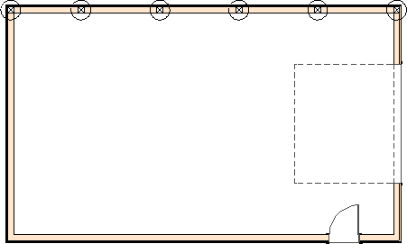
- Repeat the steps above as needed to produce posts with footings around the perimeter of the structure.
Be sure to pull the post layout from the same end of the structure so that the roof trusses will align properly later.
- Position posts on either side of the man door, leaving room for the 1 1/2" trimmers.
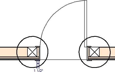
- To set their position, draw CAD Lines to serve as reference.
- Use the Copy/Paste
 and Point to Point Move
  edit tools to make a copy of a post and footing on each side of the door.
- Use the same process to places posts on either side of the garage door, leaving 3" for double trimmers.
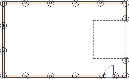
- Select Build> Floor> Build Foundation
 from the menu, then click OK to build a monolithic slab foundation using the default settings that were created earlier.
With the poles laid out, trimmers and headers for the doors can be added. Using the method described here, you can also build jamb furring if you wish.
To frame the doors
-
Zoom
 in on the man-door, then:
- Click on the post on the left-hand side of the door to select it.
- Create a copy of the selected pole directly to its left using any method that you choose.
- Click on the newly copied pole to select it, then click the Open Object
 edit button. On the General panel of the Framing Specification (Post) dialog:
- Change Width 1 to 5 1/2" and Width 2 to 1 1/2"
- Remove check-mark from Raise/Lower.
- Set the Bottom Height to 0" and then lock it.
- Change the Top Height so that it is equal to the door height plus its rough opening. In this example, a Top Height of 82" is used.
- On the Line Style panel, click Define button under the Layer heading and place the trimmer on a new custom layer, Framing, Door Trimmers.
- Click OK to close the dialog and apply your changes.
- With the post - now a trimmer - still selected, click the Point to Point Move
 edit button and move it to the outside edge of the nearest post, which is acting as the king stud.
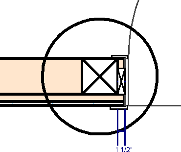
- With the trimmer still selected, click the Copy/Paste
 edit button, then use the Reflect About Object
  edit tool to make a copy that lines up with the edge of the post on the other side of the door.
- Repeat the steps above to make trimmers for the garage door.
- To change the orientation of the trimmer, reverse its Width 1 and Width 2 values rather than rotate it.
- Specify a Top Height of 122".
- Make a copy of the first trimmer next to the original to create a double trimmer configuration.
- Hold Shift and select the two trimmers and use Copy/Paste
 and Reflect About Object
  to create the trimmers for the other side of the garage door.
- Select Build> Framing> General Framing
 from the menu, then draw a framing member between the two posts on either side of the garage door to create a header.
- Click on the header to select it and click the Open Object
 edit button. On the General panel of the Framing Specification (General Framing) dialog:
- Lock the Depth and set the Bottom Height to 122".
- Specify the Width as 3 1/2". This thickness is the equivalent of two 1 3/4" LVL members laminated.
- Click the Type drop-down list and select LVL.
- On the Line Style panel, click the Define button under the Layer heading and place the beam on a new custom layer: Framing, Headers.
- Click OK to close the dialog box and apply your changes.
- Once it is resized, use the Point to Point Move
 edit tool to position the header exactly along the exterior edge of the trimmers.
- Use the same process to create a header over the man-door.
- Although not required structurally, in this example the man-door header is also using LVL. The Depth is 11 7/8", the Bottom Height is 82", and the Width is 3 1/2".
- After the header piece is created, position it on the outermost edge of the trimmers with the Point to Point Move
 edit tool.
- Select 3D> Create Orthographic View> Framing Overview
 to see the results so far.
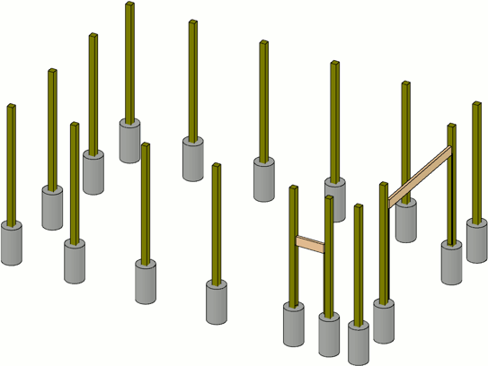
Once the poles and door framing is complete, girts can be added. The base girts can serve as the form for the concrete floor if you wish.
To create the door-level girts
- Return to floor plan view and select Tools> Layer Settings> Display Options
 from the menu to open the Layer Display Options dialog:
- Create a layer called Framing, 2 X 6 TRT Girt (Base).
- Create another layer called Framing, 2 X 6 FIR Girt.
- Turn off the display of the Framing, Headers and Walls, Normal layers.
- Lock the Footings, Post layer but leave it set to display.
- Click OK to close the dialog and apply your changes.
- Select Build> Framing> General Framing
 from the menu, then click and drag to draw a framing member along the length of each wall.
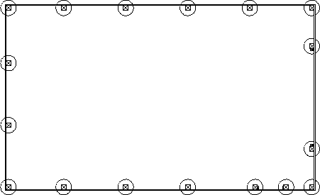
- Position these base girts so they are located just outside of the posts.
- The girt ends should line up so that they lap (or interlock) on the corners.
- Hold Shift and click to group-select the four girts and click the Open Object
 edit button. In the Framing Specification (General Framing) dialog:
- On the General panel, set the Depth to 5 1/2", then Lock the Depth and set the Top Height to 0".
- On the Line Style panel, place the girts on the new Framing, 2 X 6 TRT Girt (Base) layer.
- On the Materials panel, select a Pressure Treated Lumber material from the Library Browser.
- Click OK to close the dialog and take a moment to confirm that all four girts are still positioned correctly.
- With the four base girts still selected, click the Transform/Replicate Object
 edit button and:
- Check the box beside Copy and specify 1 copy.
- Check the box beside Move and specify 24" as the Z Delta value.
- The newly created girts will be selected. Click the Open Object
 edit button to open the Framing Specification (General Framing) dialog:
- On the General panel, confirm that the Top Height is set at 24".
- On the Line Style panel, click the Define button under the Layer heading to open the Layer Display Options dialog. Turn off the display of the Framing, 2 X 6 TRT Girt (Base) layer, and click OK.
- Select Framing, 2 X 6 FIR Girt from the Layer drop-down list.
- On the Materials panel, specify the material as regular Fir Framing.
- Click OK to close the dialog and apply your changes.
- With the four untreated girts still selected, use the Transform/Replicate Object
 edit tool to make additional girt rows as needed at the desired Z Delta interval.
- In this example, 3 more copies are made at 24" intervals in the Z Delta.
To clip the girts at the doors
- In floor plan view, select CAD> Lines> Draw Line
 from the menu, then click and drag to draw CAD lines on either side of the man-door.
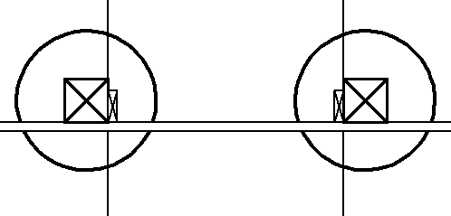
- Position the CAD lines where the girts should be cut to allow access through the door.
- In this example, the girts are clipped 1 1/2" from the door so a continuous vertical furring strip of that width can be applied to the trimmers.
- Hold Shift and select the two CAD lines, then click the Trim Objects
 edit button.
- Click and drag a cut line between the two CAD lines that crosses the girts.
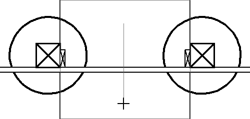
- When you release the mouse button, the girts will be trimmed to the outside of the two CAD lines and the CAD lines can be deleted.
- Repeat these steps to cut the girts around the garage door.
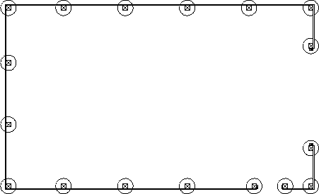
Additional girts can now be added to reach the top of the 12' high walls.
To add girts above the door levels
- Select Edit> Default Settings
 from the menu and open the Layer Set Defaults dialog.
- Click the Backclipped Sections drop-down and select 3D Framing Set from the list.
- Click the Define button to the right of the Backclipped Sections drop-down and in the Layer Display Options dialog, turn on the Framing, 2 X 6 TRT Girt (Base) and Framing, 2 X 6 FIR Girt layers in this layer set.
- Click OK to return to the Layer Set Defaults dialog, then click OK to close it, and then click Done in the Default Settings dialog.
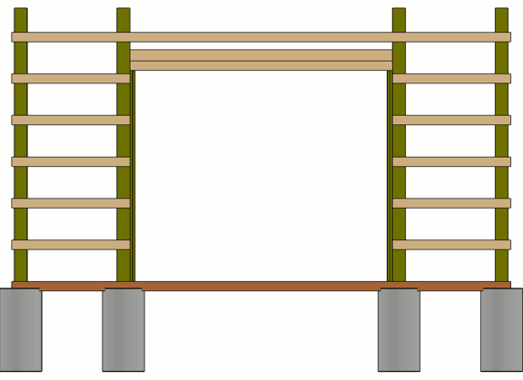
- Create a Backclipped Cross Section
 of the exterior of the man-door wall, and notice that the 3D Framing Set is active instead of the usual Section View Set layer set.
- Select the top-most girt on the right side of the man-door.
- Click the Open Object
 button and change the Bottom Height to 82" and click OK.
- Use the edit handles to move the girt to the left, in front of the header. Then resize it to fit between the posts.
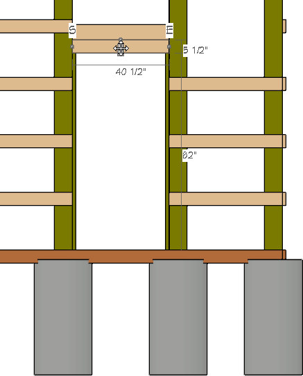
- Select the top-most girt on the left side of the wall and use its edit handles to extend it to the outside of the corner pole on the right.
If you have trouble precisely placing the Girts, turn off the Snap Grid and then use the Point to Point move tool.
- With the top girt still selected, use the Transform/Replicate Object
 tool to create two more copies in the Z delta at 24" intervals.
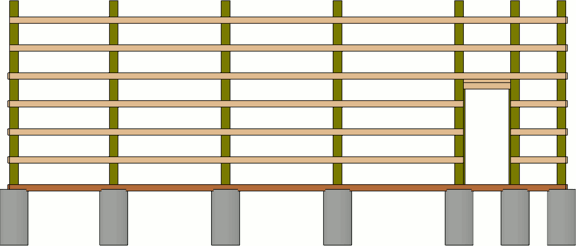
- Close this view and then create a new Backclipped Cross Section
 camera arrow through the garage door wall from exterior to interior.
- Hold Shift and select the two highest girts on each side of the door and use the Transform/Replicate Object
 edit tool to create two copies at 24" intervals in the Z delta.
- Select one of the highest girts and click the Open Object
 edit button to set the Bottom Height to 122".
- Use the edit handles to move the girt in front of the door header, and resize it to fit between the posts.
- Select the remaining highest girt and use its edit handles to extend it to the outside of the opposite corner pole.
- Close this view and create an Orthographic Framing Overview
 .
.
- Hold Shift and select the highest girts in each of the two walls that do not have doors.
- Use the Transform/Replicate Object
 edit tool to create two copies at 24" intervals in the Z Delta.
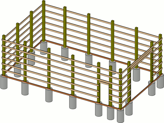
As part of the process of drawing the girts, the horizontal door furring has been created. Vertical furring should also be added.
To finish the door furring
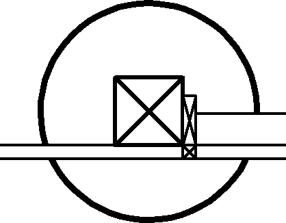
- Return to floor plan view and select one of the man-door trimmers.
- Use the Transform/Replicate Object
 edit tool to create one copy directly in front of the original - in this example, -1 1/2" in the Y Delta.
- Use this new furring strip's edit edit handles resize it and create a 1 1/2" X 1 1/2" vertical furring strip in the girt layer of the wall.
- Use the Copy/Paste
 and Point to Point Move
  edit tools to create the furring strip on the other side of the door.
- Select one of the garage door trimmers and repeat the process described above, replicating the trimmer along the X Delta rather than the Y.
To build the roof
- Open the Layer Display Options
 dialog and:
- Turn on the display of the Walls, Normal layer.
- Turn off the display of the Footings, Post layer.
- Hold down the Shift key and click to group-select the Framing layers and Lock them.
- Specify the two end walls in the plan as Full Gable Walls on the Roof panel of the Wall Specification dialog.
- In this example, the wall with the Garage door and the wall opposite it are specified as Full Gable Walls.
- Select Build> Roof> Build Roof
 from the menu. On the Options panel of the Build Roof dialog, check the box beside Boxed Eave.
- On the Structure panel under the Roof Layers heading:
- Click Edit next to Surface and change the surface(1:) thickness to 3/4" and the sheathing(2:) to 1/2".
- Specify the material for both the surface and sheathing layers, in this example, the surface material is Grey Standing Seam metal roofing and the sheathing layer set to Insulation Foam.
- Click OK to return to the Build Roof dialog.
- Remove the check from Use Room Ceiling Finish.
- Still on the Structure panel under the Roof Size heading:
- Set the Rafter to 1 1/2" X 5 1/2".
- Set the Ridge to 1 1/2" X 5 1/2".
- Set the Gable Fascia to 1/8" X 7 1/4".
- Set the Eave Fascia to 1/8" X 7 1/4".
- On the Gutter panel of the Build Roof dialog, Delete the gutter.
- On the Materials panel of the Build Roof dialog, specify materials for the Ridge Cap and Fascia components.
- In this example, the Ridge Cap material is Color - Contract.
- The Fascia color is Color - White.
- On the Roof panel of the Build Roof dialog:
- Check the box beside Build Roof Planes.
- Click OK to close the dialog and generate a roof over your structure.
- Open the Layer Display Options
 dialog and lock the Roof Planes layer so that you can build and edit roof framing without the roof planes interfering with your work.
To create the roof trusses
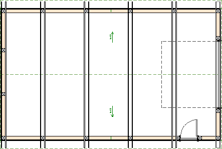
- Select Build> Framing> Roof Truss
 from the menu, then click and drag to draw a roof truss near the gable wall opposite the garage door wall.
- Click on the roof truss to select it, then use the Move
 edit handle to position it against the poles within the left gable wall.
- With the truss selected, use the Transform/Replicate Object
 edit tool to make one copy -9" in the X Delta, which will put it on the outer edge of the posts, above the girts.

- 9" is the total thickness of the posts (7 1/2") plus the thickness of the truss (1 1/2").
- If your outer truss does not sit above the girts, it is likely that your custom wall type does not have its girts layer set as the Main Layer.
- Hold Shift and select the two trusses, then use the Copy/Paste
 and Point to Point Move
  edit tools to create identical copies on the opposite end of the structure.
- With the two newly created trusses still selected, use the Transform/Replicate Object
 edit tool to create four copies at -96" intervals in the X Delta.
- Select the outermost truss on the left-hand side of the building and click the Open Object
 edit button. On the General panel of the Roof Truss Specification dialog:
- Check the box beside End Truss.
- Check the box beside Force Truss Rebuild.
- Click OK to close the dialog and implement the change.
- Select the outermost truss on the right-hand side of the building and use the same steps to convert it to a Gable End Truss.
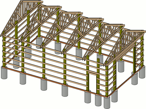
Both upper and lower blocking for the roof trusses can now be created.
To create lower truss blocking
- Open the Layer Display Options
 dialog and lock the Framing, Roof Trusses layer so that you can add blocking without difficulty.
You may wish to lock or turn off the display of additional layers, such as "Walls, Normal," to make drawing truss blocking easier.
- Click CAD> Lines> Draw Line
 , and draw a line along the ends of the trusses as a reference.
- Select Build> Framing> General Framing
 from the menu, then click and drag to draw a framing member in the space between the roof trusses over the back gable wall. Position it between the corner post and the eave edge.
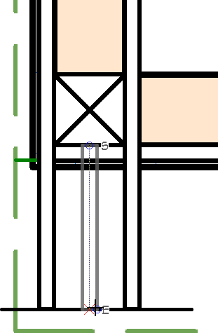
- Click on the framing member to select it and use its edit handles to:
- Adjust its length as needed so it butts against the post and aligns with the ends of the trusses.
- Increase its width so it touches trusses on either side.
- When you are finished, you can Delete
 the CAD line.
- Click on the framing member to select it and click the Open Object
 edit button. On the General panel of the Framing Specification (General Framing) dialog:
- Set the Depth to 1 1/2" and Lock it.
- Set the Bottom Height to 144" and then Lock it.
- Select the Lock Start radio button.
- Verify that the Width is 7 1/2".
- On the Line Style panel of the Framing Specification (General Framing) dialog:
- Click the Define button under the Layer heading and place the framing member on the a new Framing, Lower Roof Blocking layer.
Put a check-mark in the Framing, Roof Blocking layer to display this layer and remove the Lock so that you can modify items on this layer, and then click OK.
- Under the Drawing Group heading, select 1 - Front from the drop down menu.
- On the Fill Style panel of the Framing Specification dialog:
- Select Angle Hatch from the Fill Pattern drop-down list.
- Specify a light grey color for the Color.
- Click OK to close the dialog and apply your changes.
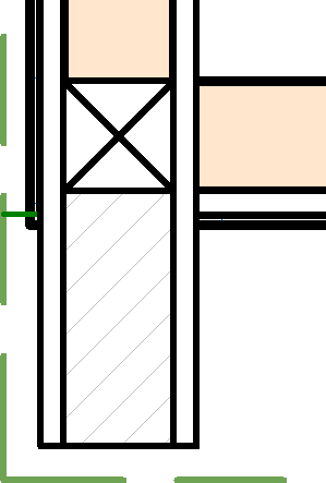
- With the framing member still selected, use the Copy/Paste
 and Point to Point Move
  edit tools to position an exact copy on the other side of the pole.
- Use the newly copied framing member's edit handles to resize it so it reaches the next pole.
- Repeat this process to create five lower truss blocks over the back gable wall.
- Hold Shift and group select the five lower truss blocks created thus far and use the Copy/Paste
 and Reflect About Object
  edit tools to make copies of these blocks between the trusses at the opposite wall.
- With the newly copied lower truss blocks selected:
- Hold Shift and click on the middle block that crosses the roof ridge to remove it from the selection set.
- Click on one of the blocks adjacent to the middle block to remove it from the selection set, as well.
- Then, with three blocks still selected, use the Transform/Replicate Object
 edit tool to create four more copies at -96" on the X Delta.
- Use these new blocks' edit handles to extend them across the structure, from post to post.
- Edit the blocks over the garage wall so they bump against the posts rather than draw over them.
This is what the lower blocking will look like with all other layers turned off:

To create the upper roof truss blocking
- Open the Layer Display Options
 dialog and turn off the Framing, Roof Blocking layer.
- Select Build> Framing> Rafter
 from the menu, then click and drag to draw a rafter between the eave and the ridge of the roof.
- This rafter will serve as the first upper roof truss block and its exact position is not important right now.
- You may be prompted to turn on the display of and unlock the Framing, Roof Rafters layer, and you will want to do so.
- Select the rafter and click the Open Object
 edit button. On the General panel of the Framing Specification (Rafter) dialog:
- Specify the Depth to be 1 1/2".
- Specify the Width to be 7 1/2", which is the thickness of the poles.
- On the Line Style panel:
- Click the Define button under the Layer heading and create a new Framing, Upper Roof Blocking layer, then click OK.
- Under the Drawing Group heading, select 1 - Front from the drop-down menu.
- On the Fill Style panel:
- Select Angle2 Hatch from the Fill Pattern drop-down list.
- Specify a dark grey color for the Fill Color.
- Click OK to close the dialog and apply your changes.
- With the new upper block selected, use the Point to Point Move
 edit button to position the new upper truss blocking member between the two trusses in the back gable wall.
- Using its edit handles, move the upper truss block's eave end so it lines up with the truss ends.
- With the upper block still selected, use the Copy/Paste
 and Reflect About Object
  edit tools to make a copy of the block on the other side of the roof ridge.
- Hold Shift and select the two upper blocks on the left side of the structure and use the Copy/Paste
 and Reflect About Object
  edit tools to make copies of the blocks over the opposite wall.
- With the two upper blocks on the right side of the structure selected, use the Transform/Replicate Object
 edit tool to create four copies at -96" intervals in the X Delta.
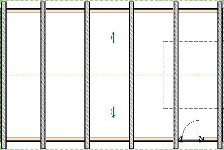
To generate the sub-fascia
- Open the Layer Display Options
 dialog and:
- Unlock the Roof Planes layer.
- Turn off the Framing, Upper Roof Blocking layer.
- Select Build> Roof> Edit All Roof Planes
 from the menu. On the Structure panel of the Roof Plane Specification dialog:
- Check the box beside Build Roof Framing.
- Set the Rafter Spacing to equal the full length of the structure to prevent additional rafters from generating. In this example, 480" is specified.
- Verify that Trim to Soffits is checked.
- Uncheck the box beside Lookout.
- Verify that Gable Fascia is checked and change Width to 1/8" and the Depth to 5 5/8".
- Verify that Eave Fascia is checked and change the Width to 1/8" and the Depth to 5 5/8".
- Click OK to close the dialog and build fascia.
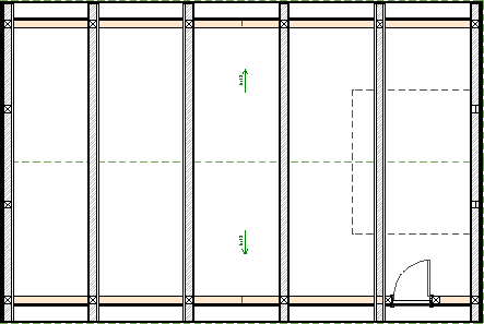
To draw the purlins
- Select Build> Framing> Roof Blocking
 from the menu.
- Click and drag to draw a Roof Blocking member between the pair of trusses over the back gable wall and the pair of trusses over the garage door wall. Position the Roof Blocking, or purlin, in the overhang area of the trusses.
- Select the purlin and click the Open Object
 edit button.
- On the Line Style panel, click the Define button under the Layer heading and:
- Turn off the display of the Framing, Roof Blocking layer.
- Create a new layer called Framing, Roof Purlins select it and click OK to place the purlins on this layer.
- On the Fill Style panel:
- Select Solid from the Fill Pattern drop-down list.
- Select a pale brown Fill Color.
- Click OK to exit the dialog saving the changes.
- Position the purlin 8" inside the Eave Sub Fascia.
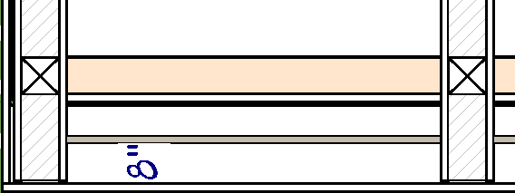
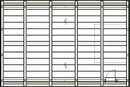
- Use the Multiple Copy
 edit tool to make six copies of the purlin in the direction of the roof ridge. Note that the default Multiple Copy Interval is 24" for Rafters.
- Repeat these steps to create purlins on the opposite side of the roof.
To extend the end poles
- Create an exterior Backclipped Cross Section
 view of one of the gable walls.
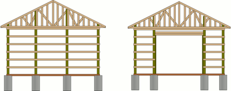
- Click on one of the poles in the gable wall to select it near its top edge, then use the edit handles to extend it upward to the top chord of the trusses.
- When all posts reach the height of the truss top chords, select close the view.
- Repeat this process on the opposite gable wall.
To create 3D views
3D views of the structure can be produced using any of the 3D tools. Bear in mind that by default, the Framing layers are turned off in the layer sets assigned to all camera views aside from Framing Overviews. If you want the posts and other items to display in a particular type of 3D view, create the view and then open the Layer Display Options dialog and turn on the desired layers.
Return To Top

 from the menu to open the Default Settings dialog.
 from the menu. On the Roof panel of the Build Roof dialog:
 from the menu. Give the file a short, descriptive name such as "Pole Structure Template", and save it in the Chief Architect Templates directory, or the location of your choice.
 , then click and drag to draw shape of the perimeter.
 edit button. In the Room Specification dialog:
 from the menu, then click on a wall to place a door. Starting in X11, barn doors can be added without using a library object by going to Build> Door> Barn Door
  from the menu, then click on the left wall to place a garage door at that location.
 edit button, then click inside the room to center the door along the wall.
 in on one of the corners on the right side of the structure, select Build> Framing> Post with Footing
  and click to place a post with a footing close to the intersection of the two walls.
 edit tool to position the post precisely in the corner of the 7 1/2" main wall layer.
 are enabled - particularly Endpoint Snaps
  edit button. On the General panel of the Framing Specification (Post) dialog:
 tool, click on the footing to select it, then click the Open Object
  edit button. On the General panel of the Slab Specification dialog:
 edit button. In the Transform/Replicate Object dialog:
 edit tool to position them at the nearest wall intersection, as in step 2, above.

 and Point to Point Move
  edit tools to make a copy of a post and footing on each side of the door.
 from the menu, then click OK to build a monolithic slab foundation using the default settings that were created earlier.
 in on the man-door, then:
 edit button. On the General panel of the Framing Specification (Post) dialog:
 edit button and move it to the outside edge of the nearest post, which is acting as the king stud.
 edit button, then use the Reflect About Object
  edit tool to make a copy that lines up with the edge of the post on the other side of the door.
 and Reflect About Object
  to create the trimmers for the other side of the garage door.
 from the menu, then draw a framing member between the two posts on either side of the garage door to create a header.
 edit button. On the General panel of the Framing Specification (General Framing) dialog:
 edit tool to position the header exactly along the exterior edge of the trimmers.
 edit tool.
 to see the results so far.
 from the menu to open the Layer Display Options dialog:
 from the menu, then click and drag to draw a framing member along the length of each wall.
 edit button. In the Framing Specification (General Framing) dialog:
 edit button and:
 edit button to open the Framing Specification (General Framing) dialog:
 edit tool to make additional girt rows as needed at the desired Z Delta interval.
 from the menu, then click and drag to draw CAD lines on either side of the man-door.
 edit button.

 from the menu and open the Layer Set Defaults dialog.
 of the exterior of the man-door wall, and notice that the 3D Framing Set is active instead of the usual Section View Set layer set.
 button and change the Bottom Height to 82" and click OK.
 tool to create two more copies in the Z delta at 24" intervals.
 camera arrow through the garage door wall from exterior to interior.
 edit tool to create two copies at 24" intervals in the Z delta.
 edit button to set the Bottom Height to 122".
 .
. edit tool to create two copies at 24" intervals in the Z Delta.
 edit tool to create one copy directly in front of the original - in this example, -1 1/2" in the Y Delta.
 and Point to Point Move
  edit tools to create the furring strip on the other side of the door.
 dialog and:
 from the menu. On the Options panel of the Build Roof dialog, check the box beside Boxed Eave.
  dialog and lock the Roof Planes layer so that you can build and edit roof framing without the roof planes interfering with your work.
 from the menu, then click and drag to draw a roof truss near the gable wall opposite the garage door wall.
 edit tool to make one copy -9" in the X Delta, which will put it on the outer edge of the posts, above the girts.
 and Point to Point Move
  edit tools to create identical copies on the opposite end of the structure.
 edit tool to create four copies at -96" intervals in the X Delta.
 edit button. On the General panel of the Roof Truss Specification dialog:
 dialog and lock the Framing, Roof Trusses layer so that you can add blocking without difficulty.
 , and draw a line along the ends of the trusses as a reference.
 from the menu, then click and drag to draw a framing member in the space between the roof trusses over the back gable wall. Position it between the corner post and the eave edge.
 the CAD line.
 edit button. On the General panel of the Framing Specification (General Framing) dialog:
 and Point to Point Move
  edit tools to position an exact copy on the other side of the pole.
 and Reflect About Object
  edit tools to make copies of these blocks between the trusses at the opposite wall.
 edit tool to create four more copies at -96" on the X Delta.
 dialog and turn off the Framing, Roof Blocking layer.
 from the menu, then click and drag to draw a rafter between the eave and the ridge of the roof.
 edit button. On the General panel of the Framing Specification (Rafter) dialog:
 edit button to position the new upper truss blocking member between the two trusses in the back gable wall.
 and Reflect About Object
  edit tools to make a copy of the block on the other side of the roof ridge.
 and Reflect About Object
  edit tools to make copies of the blocks over the opposite wall.
 edit tool to create four copies at -96" intervals in the X Delta.
 dialog and:
 from the menu. On the Structure panel of the Roof Plane Specification dialog:
 from the menu.
 edit button.
 edit tool to make six copies of the purlin in the direction of the roof ridge. Note that the default Multiple Copy Interval is 24" for Rafters.
 view of one of the gable walls.