The information in this article applies to:

QUESTION
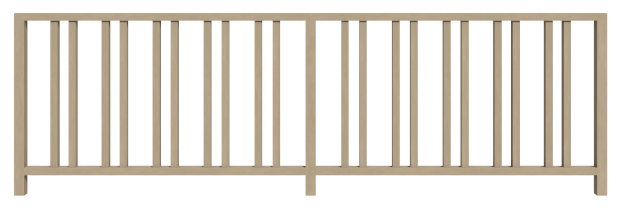
I have a custom railing I need to create for a client. How can I create custom balusters and panels?

ANSWER
Custom railing panels, newels, and balusters can all be created using shapes or solids, and then converting them into millwork symbols, allowing them to be used in the Railing Specification dialog.
This article discusses how to create different space intervals for balusters and creating a custom panel. Newels, balusters, and panels can be created with any 3D item that has been added to the library as millwork. For this example, 3D solids are used.
To create a custom baluster or newel
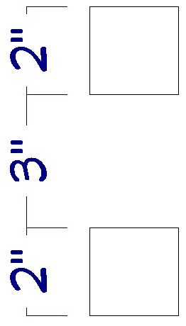
- S elect Build> 3D Solid> 3D Solid
 , and click and drag to draw two 3D solids 2" in size, spaced vertically, 3" apart.
In X15 and prior versions, navigate to Build> Primitive> 3D Solid instead.
When creating a custom newel or baluster, it's imperative that it's drawn vertically in the drawing space. Otherwise you will need to rotate the symbol before it's applied to a railing.
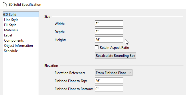
- Group select the two solids, click the Open Object
 tool to open the 3D Solid Specification dialog, specify the Height as 36", which will act as the total height of the baluster, then click OK.
Materials can be specified on the Materials panel at this time, if desired. If materials are not changed now, it's possible to change them later when the balusters are applied to the railing.
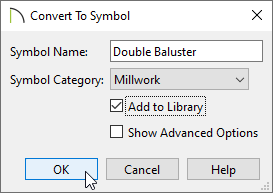
- With the two objects still group selected, click on the Convert Selected to Symbol
 edit tool.
- In the Convert To Symbol dialog, specify an appropriate Symbol Name, select Millwork from the Symbol Category drop-down menu, check the Add to Library box , then click OK.
In this example, the name "Double Baluster" is used.
- This millwork item will now be added to the User Catalog section of the Library Browser, and it will be following your cursor waiting to be placed. Click the Select Objects
 tool to deselect the newly created object.
To create a custom panel
Panels can be created using a single 3D solid with a hole cut into it, or by using several pieces put together.
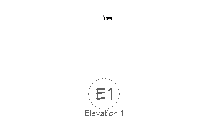
- In an empty area of your plan, select 3D> Create Orthographic View> Cross Section/Elevation
 , then click and drag to create a view.
When creating a custom railing panel, it's imperative that it's drawn horizontally in the drawing space. Otherwise you will need to rotate the symbol before it's applied to a railing.
- In the cross section/elevation view, select Build> 3D Solid> 3D Solid from the menu, then click and drag to create a 3D solid the desired size for the panel.
In X15 and prior versions, navigate to Build> Primitive> 3D Solid instead.
Materials can be specified on the Materials panel of the 3D Solid Specification dialog now, or you can wait and change the material when you apply the symbol to your railing.
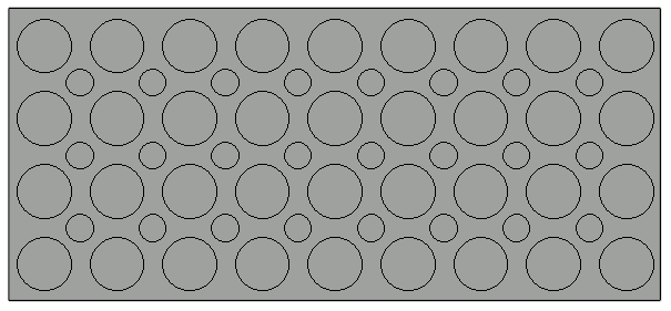
- Next, select CAD> Circles> Circle
 and click and drag several circles within the 3D solid, of which will be cut out to create several holes. Continue drawing circles or other shapes that will be cut out of the solid.
You may want to use a variety of edit tools, such as Multiple Copy  , Transform/Replicate Object
  , and Align/Distribute Along Line
  to create copies of the circle or preferred shape within this panel.
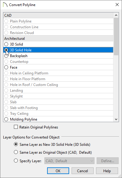
- Group select the CAD circles, click the Convert Polyline
 edit button, and in the Convert Polyline dialog that opens, select 3D Solid Hole from the list, then click OK.
- In the 3D Solid Specification that opens next, ensure that the holes have been cut, the dimensions for the panel are to your liking, then click OK. Your panel may now look similar to the image below.

- Select the 3D solid panel using the Select Objects tool, then click the Convert Selected to Symbol edit tool.
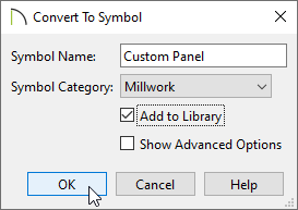
- In the Convert To Symbol dialog, specify an appropriate Symbol Name, select Millwork from the Symbol Category drop-down menu, check the Add to Library box , then click OK.
In this example, the name "Custom Panel" is used.
- This millwork item will now be added to the User Catalog section of the Library Browser, and it will be following your cursor waiting to be placed. Click the Select Objects tool to deselect the newly created object.
To apply the custom baluster, newel, or panel to a railing
- Select an existing railing or select Build> Railing and Deck> Straight Deck Railing
 or Straight Railing
  , then click and drag to create a railing.
- With the railing selected, click the Open Object edit tool.
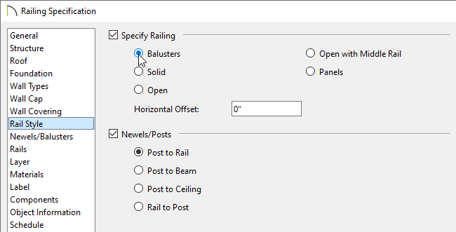
- On the Rail Style panel of the Railing Specification dialog that opens, select either Balusters or Panels under the Specify Railing section.
In this example, Balusters is selected.
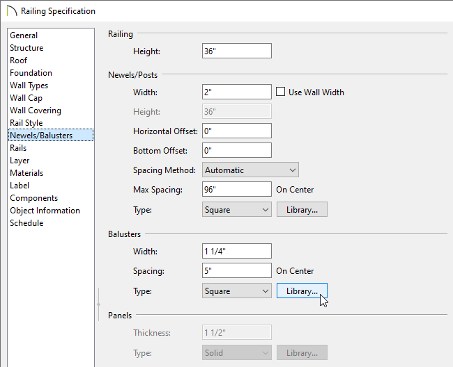
- On the Newels/Balusters panel, there are different sections for Newels/Posts, Balusters, and Panels. Depending on the option chosen in Step 3, either the Balusters or Panels section will be grayed out.
- To specify a custom Newel/Post, click the Library button next to the Type option in the Newels/Posts section.
- To specify a custom Baluster, click the Library button next to the Type option in the Balusters section.
- To specify a custom Panel, click the Library button next to the Type option in the Panels section.
- In the Select Library Object dialog which opens next, browse to the User Catalog and select the custom baluster, newel, or panel created earlier, then click OK.
- Back in the Railing Specification dialog, it may be necessary to adjust spacing - for example, if you chose the "Double Baluster" created in the first section of this article, you might want to set the Width to 5" and the Spacing to 12".
- Once all desired changes have been made, click OK and create a Camera
 view to see the results.