QUESTION
I want to create a belly band around a structure that I am designing. How can I do that?

ANSWER
Creating a belly band, sometimes referred to as a mid-section trim, is easy using the Make Room Molding Polyline edit tool.
Creating a belly band automatically
- Click the Select Objects
 button, then click just outside of an exterior wall to select the Exterior Room of the structure.
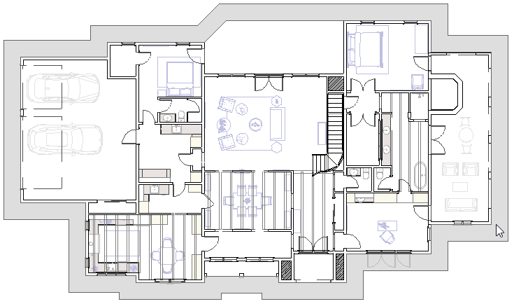
- When the Exterior Room is selected, its name appears on the left side of the Status Bar and the exterior of the structure is highlighted.
- If you select the wall or other object on accident, click the Select Next Object
 edit button or press the Tab key on your keyboard until the exterior of the structure becomes highlighted.
- With the Exterior Room selected, click the Make Room Molding Polyline
 edit button to display the Make Room Molding Polyline dialog.
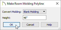
- Select Blank Molding from the Convert Molding drop-down list.
- Set a Height value, which specifies how high you want the molding to be off the floor.
- Click OK to close the dialog and create a molding polyline around the structure's exterior.
- With the newly created Molding Polyline selected, click the Open Object
 edit button to open the Molding Polyline Specification dialog.
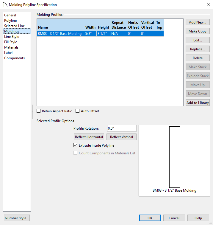
- On the Moldings panel, click the Add New button to display the Select Library Object dialog and browse for a molding profile of your choice.
In this example, the BM03 - 3 1/2" Base Molding is selected.
- Specify the desired Width, Height, and Offsets.
- Select the Materials panel, click on the Molding component, and specify the material that you want for this molding.
- When you have finished, click OK.
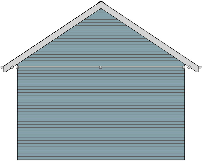
- Create a Perspective Full Overview
 to see the results.
Creating a belly band manually
- Create a Cross Section/Elevation
 of the side of the structure where you would like to create belly band trim.
- Navigate to Build> Trim> Molding Line
 , then click and drag to create your trim board using the molding line.
In X15 and prior versions, use the 3D Molding Line tool instead.
- Using the Select Objects tool, click to select the molding line.
- When the molding line/polyline is selected, its name appears on the left side of the Status Bar and the line will have edit handles.
- If you select the wall or other object on accident, click the Select Next Object edit button or press the Tab key on your keyboard until the molding line/polyline is selected.
- With the newly created molding line selected, click the Open Object edit button to open the Molding Polyline Specification or 3D Molding Polyline Specification dialog.
- On the Moldings panel, click the Replace button to display the Select Library Object dialog and browse for a molding profile of your choice.
In this example, the BM03 - 3 1/2" Base Molding is selected.
- Specify the desired Width, Height, and Offsets.
- Select the Materials panel, click on the Molding component, and specify the material that you want to apply to this molding.
- When all desired changes have been made, click OK.
- Repeat this process until all of your desired walls have the desired belly band trim.