QUESTION
How can I add and adjust lighting in my designs?
ANSWER
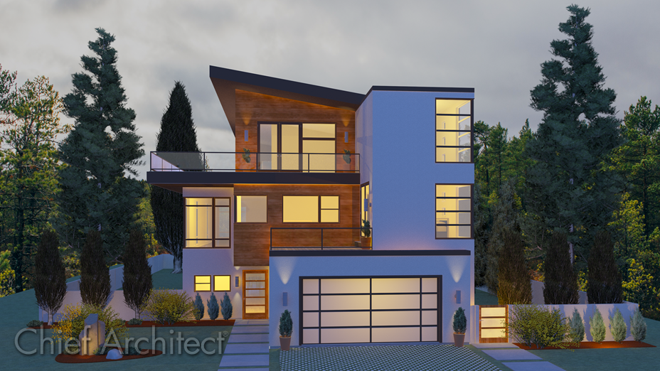
In Chief Architect, you can use lighting to help produce dramatic, photo-realistic 3D views of your model. To do so effectively though, takes an understanding of how light is generated in the program.
The following is a list of the different light sources that are used throughout Chief Architect:
-
Default Interior Lights - If you create an interior camera in a room where no lights have been placed, the program creates a Default Light Source within that room, which acts as a central point light source but cannot be selected or edited. Because it cannot be adjusted, if you want to control the light in an interior rendered view, you must add lights to the rooms in your plan by placing Light Fixtures and Added Lights.
-
Light Fixtures - An Electrical symbol that has "Specify As Light" checked in the Electrical Service Specification dialog, or a material that is defined to have an Emissive value. There are two ways a Light Fixture can add light to a scene: Light Sources (Point and Spot) and Area Light materials:
-
- Light Sources are punctual, emanating from a single point, and can either be Point lights that shine in all directions, or directional Spot lights, which emit a cone of light in a particular direction. These light work in all rendering techniques that support lighting.
- Area Lights are emissive materials that emit light from the full area of any surface they are assigned to in GPU Ray Trace views. They have a bright appearance in all rendering techniques that support lighting, but only actually add light to a scene in GPU Ray Traced Physically Based and Clay renderings.
-
Added Lights - Added Lights are light sources without 3D objects associated with them. There are two types of Added Lights: Point lights and Spot lights. Added Lights only act as light sources in plans that have at least one room defined. They display 2D symbols in plan view but do not display as objects in 3D views; however, the light's position can be represented by red crosshairs, and a blue arrow can be displayed for Spot lights, indicating the light's direction.
-
Sunlight and Moonlight - Sunlight is the only source of light in exterior daytime camera views. When Sunlight is toggled off, nighttime exterior lighting is used. In addition to Sunlight, representations of the moon and stars (Moonlight) can be seen in the sky when "Use Generated Sky" has been enabled within a Camera Specification. Sunlight must either be toggled off or the sun moved below the horizon for the moon and stars to appear.
-
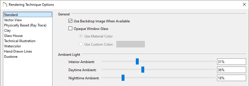
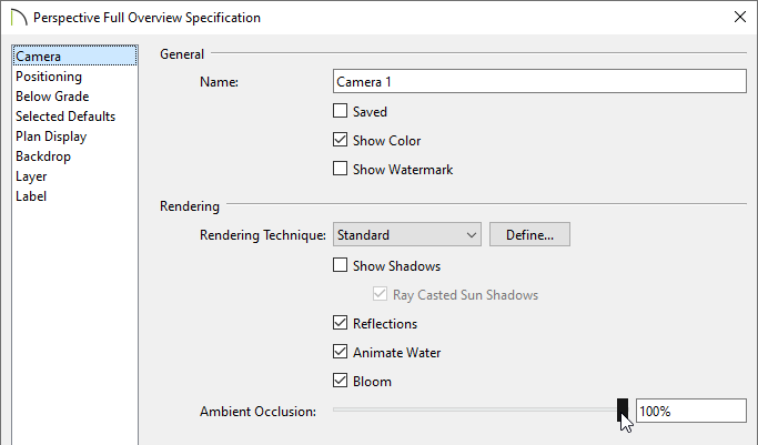
Ambient Lighting and Ambient Occlusion - Ambient Lighting simulates the way light bounces around a scene, producing a basic level of uniform illumination on all surfaces. It is used in camera views and overviews using the Standard, Duotone, and Watercolor rendering techniques and in ray trace views. There are three types of Ambient Light, all of which are controlled on the Standard panel of the Rendering Technique Options dialog. Ambient Occlusion adds shading to surfaces near corners which, because of their location, reflect less light compared to other surfaces. Too little Ambient Occlusion can result in a view having a flat appearance. This can be controlled in Standard, Duotone, Watercolor, and Physically Based renderings by accessing the Camera Specification.
-
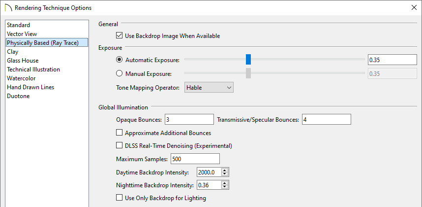
Backdrop Intensity - In Physically Based and Clay renderings, the scene's backdrop contributes to its illumination, and can be controlled using the Daytime and Nighttime Backdrop Intensity settings located in the Rendering Technique Options dialog.
With an understanding of the various light sources, you can now add lighting to your plans, then adjust the lighting to achieve your desired results:
To add lighting
There are variety of ways to add lighting to a plan:
-
Select Build> Electrical> Light
 from the menu, then click at a location where you would like to place a light fixture.
-
If you click on a wall, a wall light fixture will be created.
-
If you click away from a wall, a ceiling mounted light fixture will be placed.
-
The default electrical objects that will be placed using this tool can be specified in the Electrical Defaults.
-
Select Build> Electrical> Rope Light
 from the menu, then click and drag where you would like to have rope lighting.
- This is a great tool for under cabinet or pathway lighting.
-
This tool is only available in a 2D floor plan view.
-
To utilize materials that emit light, navigate to Chief Architect Core Catalogs> Materials> Lighting within the Library Browser
 , and apply a material to your desired 3D object to create an Area Light. You can also edit or modify materials to have emissivity:
- Navigate to 3D> Materials> Plan Materials
 , select the material that you want to modify, then click Edit. Alternatively, open a camera view, navigate to 3D> Adjust Materials> Adjust Material Definition
  , then click on the desired material in the view.
- On the Properties panel of the Define Material dialog that displays, set the Material Class to General Material, Translucent, or Transparent, then specify an appropriate Emissive value. Note that a value of 0 disables the material from being used as an Area Light.
-
Navigate to Chief Architect Core Catalogs> Architectural> Lighting within the Library Browser
 and select an electrical light fixture.
-
When you move your cursor into the drawing area, it will display the Electrical
 icon.
icon.
-
Click to place the selected library symbol in your plan.
-
Several additional light fixtures can be located in bonus and manufacturer catalogs, of which can be accessed from the 3D Library. Please see the Related Articles section to learn more about obtaining additional catalogs.
-
Select 3D> Lighting > Add Lights
 from the menu, then click once to place a Spot light or click-and-drag to place a Point light without an associated 3D object.
-
This allows you to customize the lighting in a space without adding electrical light fixtures.
-
This tool is only available in a 2D floor plan view.
- To enable/disable Sunlight, navigate to 3D> Lighting> Toggle Sunlight
 . To see Moonlight, first disable the Sunlight or move the sun to be lower than the horizon. Then, access a 3D view, navigate to Tools> Active View> Edit Active View
  , and on the Backdrop panel of the Camera Specification, check Use Generated Sky.
To adjust lighting
The process for adjusting lighting in your design will vary based on the light source that you want to change:
- To adjust Light Fixtures and Added Lights, navigate to 3D> Lighting> Adjust Lights
 . In the dialog that displays, select the Name of the light source that you want to modify, then either use the various fields that are available to edit the light, and/or click Adjust Light(s) to open the Electrical Service Specification dialog or Adjust Material(s) to open the Adjust Area Light Material dialog for further editing.
In X17 and newer versions, the brightness of light sources can be adjusted separate from the Intensity. Select one or more light sources, then click Adjust Brightness to modify the brightness.
To learn more about the various options located in this dialog, such as Light Sets, please refer to the Cameras & Lighting video category, or access your program's documentation.
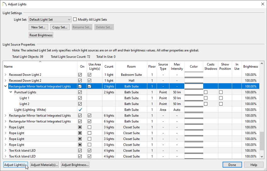
Several settings associated with Light Fixtures and Added Lights can only be modified in the Electrical Service Specification:
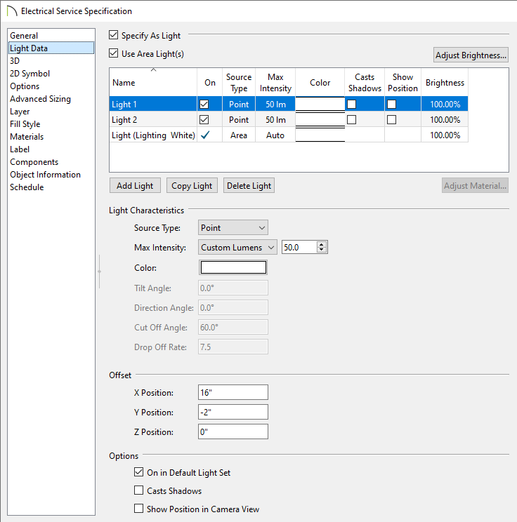
- On the General or Location panel, the size and position, the display properties, as well as the quantity and spacing (when using rope lights) can all be adjusted.
- On the Light Data panel, Light Characteristics, such as the Source Type (Spot or Point), Intensity (Lumens), and more can be specified. Tilt Angle, Direction Angle, Cut Off Angle, and Drop Off Rate are only available for Spot lights.
- Access each of the other panels in this dialog to specify additional information for the light(s). To learn more, please refer to the "Customizing a Light Fixture" resource in the Related Articles section below.
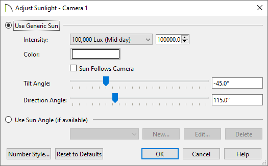
- To edit Sunlight, navigate to 3D> Lighting> Adjust Sunlight
 while in a rendered view, and in the dialog that appears, adjust the sun properties to your liking, then click OK. To edit Moonlight properties, access the Backdrop panel of the Camera Specification and enable the Use Generated Sky setting while the Sunlight is toggled off or the sun is below the horizon.
-
To adjust Ambient Light, navigate to 3D> Rendering Techniques> Technique Options
 while in a rendered view, then access the Standard panel. Adjust the ambient light settings to your liking, then click OK.
-
Interior Ambient controls the ambient light in interior views.
-
Daytime Ambient controls the ambient light in exterior views when Sunlight is enabled.
-
Nighttime Ambient controls the ambient light in exterior rendered views when Sunlight is disabled.
- To adjust Ambient Occlusion, access a 3D camera view, navigate to Tools> Active View> Edit Active View
 , and on the Camera panel, use the slider or input field to change the percentage value associated with the Ambient Occlusion setting.
Ambient Occlusion is more realistic than uniform Ambient Light, but can take longer to render.
-
To adjust Backdrop Intensity, navigate to 3D> Rendering Techniques> Technique Options
 while in a rendered view, then access the Physically Based (Ray Trace) panel. Adjust the backdrop intensity settings to your liking, then click OK.
-
Daytime Backdrop Intensity is the brightness of the view's background color or backdrop image when the Sunlight is toggled on.
-
Nighttime Backdrop Intensity is the background brightness when the Sunlight is toggled off.

 from the menu, then click at a location where you would like to place a light fixture.
 icon.
icon. from the menu, then click once to place a Spot light or click-and-drag to place a Point light without an associated 3D object.


