The information in this article applies to:

QUESTION
In our area, a lot of buildings feature what are known as Dickey Roofs. How can I create a roof like this in Chief Architect?

ANSWER
A Dickey Roof is a style of hip roof that is characterized by deep, shallow-pitched eaves combined with a steeper upper roof. They often feature Dutch gables or gable dormers and are sometimes referred to as "witches hats" as a result. This style was developed by architect C.W. Dickey specifically to address the local climate and culture of Hawaii, but it is well-suited for any hot location with wind-driven rains.
In this example, a Dickey roof with wide, shallow-pitched eaves, two steeper upper pitches, and a Dutch gable will be created.
To create a basic double-pitch roof
- Select Build> Roof> Build Roof
 from the menu.
- On the ROOF panel of the Build Roof dialog:
- Specify the Pitch value as the desired shallow pitch for the eaves. In this example, 3 in 12 is used.
- Specify the Eave and Gable Roof Overhang values. In this example, 24" eaves are used.
- Click OK to close the dialog and set these values as your defaults without actually building a roof.
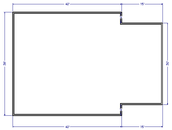
- Next, draw the exterior walls of the structure. In this example, a rectangular structure with a small bump-out is created.
- Select Build> Wall> Straight Exterior Wall
 from the menu, then click and drag a rectangular selection marquee around the structure to select all of the exterior walls at once.
- Click the Open Object
 edit button, and on the ROOF panel of the Wall Specification dialog:

- Notice that the Pitch value is 3 in 12, as specified in step 1.
- Check the box beside Upper Pitch and specify the desired Upper Pitch value. In this example, 6 in 12 is used.
- Specify where you want the roof to transition from lower to upper pitch. In this example, the transition occurs 36" In from Baseline.
- Open the Build Roof
 dialog once more by going to Build> Roof> Build Roof, check Build Roof Planes, and click OK.
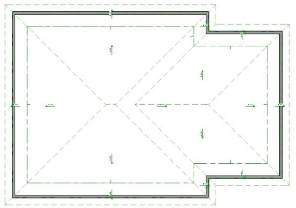
- Select 3D> Create Perspective View> Perspective Full Overview
 from the menu to see the results so far. Close
  the overview and return to floor plan view when you are finished.
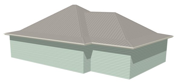
While two roof pitches can be generated automatically in Chief Architect, three cannot; so, you will need to draw the topmost roof planes manually. The first step is figuring out the height at which they should begin.
To find the upper pitch transition height
- Select 3D> Create Orthographic View> Backclipped Cross Section
 from the menu, then click and drag a camera arrow that begins in front of the structure and ends just past the roof ridge.
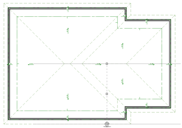
- In the elevation view that is generated, select CAD> Line> Draw Line
 from the menu, then click and drag to draw a CAD line snapped to the ridge of the roof where a third pitch will be added.
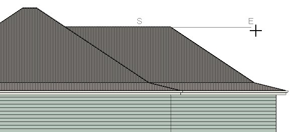
- Draw a second CAD Line
 below and parallel to the first one. Make sure it extends into the roof plane.
- Select CAD> Dimension> Manual Dimension
 from the menu, then click and drag a dimension line between the two CAD lines.
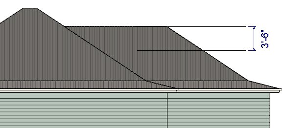
- Use the CAD lines and dimension as references to help determine where you would like the topmost pitch to begin.
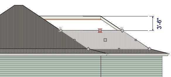
- Click the Select Objects
 button, then click on the roof plane to select it. Use the resize edit handle on the top edge to drag it downward until it snaps to the lower CAD line.
- Select Window> Swap Views
 to return to floor plan view without closing the elevation view.
To draw the topmost roof planes
- Select Build> Roof> Roof Plane
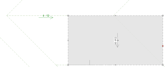
 from the menu, then draw a roof plane adjacent to the ridge edge of the roof plane that you just modified. To do this:
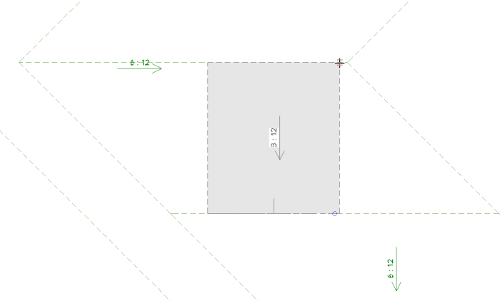
- Click and drag along the ridge edge of the roof plane.
- Release the mouse button and move the mouse pointer upslope, towards the location of the ridge.
- When the pointer snaps to the ridge line of the opposite roof plane, click once.
- Select the newly created roof plane and click the Open Object
 edit button to open the Roof Plane Specification dialog, and on the ROOF panel, make sure that the Baseline Height is locked and then change the Pitch to 8 in 12.
- With the roof plane still selected, use the edit handles to extend the side edges out until the corner snaps to the edge of the roof plane below it.
- Create a Perspective Full Overview
 to see the results so far. Close
  the view when you are finished.
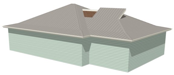
- If the new roof plane's height meets your needs, proceed to step #6. If it does not:
-
Delete
 the new roof plane.
- Return to the elevation view and try a different pitch transition height.
- Draw a new topmost Roof Plane
 as described above.
- When you are satisfied with the upper roof's proportions, you can Close
 the elevation view without saving it.
- Add an extra edge to the roof plane adjacent to the topmost roof plane's side so the two can be meet at a geometrically correct valley. To do this:
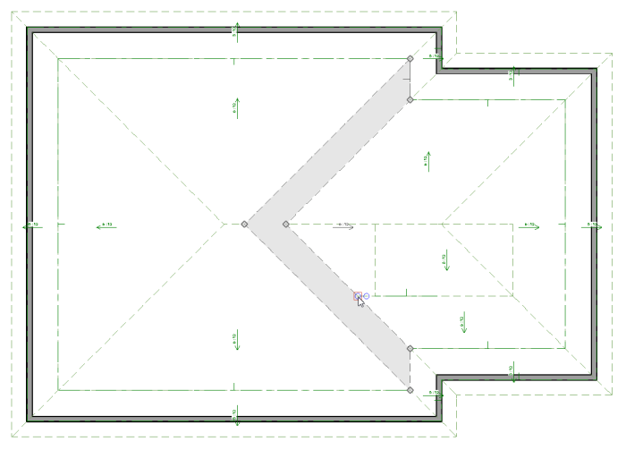
- Click on the adjacent roof plane to select it, then click the Break Line
 edit button.
- Click on the edge of the roof plane where the topmost roof plane's corner meets it to create a new corner edit handle at that location.
- Use the Join Roof Planes
 edit tool to join the topmost roof plane with the roof plane adjacent to its side. To do this:
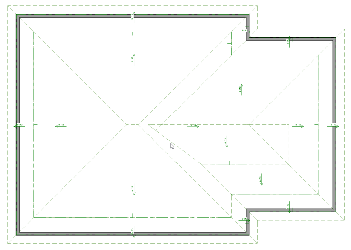
- Select the edge of the roof plane upslope from the new edit handle created in step 6.
- Click the Join Roof Planes
 edit button.
- Click once on the adjacent edge of the topmost roof plane. The program will automatically join the two planes along a geometrically correct line.
- Next, make a reflected copy of the topmost roof plane on the other side of the ridge. To do this:
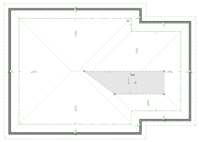
- Select the roof plane and click the Copy/Paste
 edit button.
- Click the Reflect About Object
 edit button, then move your mouse pointer over the topmost roof plane's ridge line.
- When a dashed reflection axis displays over the top of the ridge line, click once.
- Repeat step 6, above, to join this new roof plane to the plane adjacent to its side.
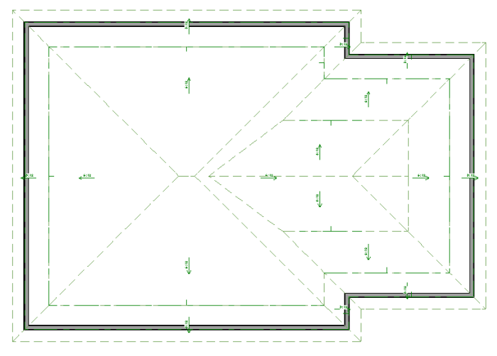
Once the topmost roof planes are in place, a Dutch gable can be added beneath them.
To add a Dutch gable
- Go Up One Floor
 and turn on the Reference Display
  . Notice that the portion of the roof that the topmost roof planes overlap is represented by a triangle.
- Select CAD> Line> Draw Line
 from the menu, then:
- Click and drag to draw a line along the downslope base of the triangle.
- Draw a second line, parallel to the first, within the triangle area.
- Select the second CAD line and use the temporary dimension that displays to position it so that its distance from the first line equals the depth of the eave that you would like for the Dutch gable.
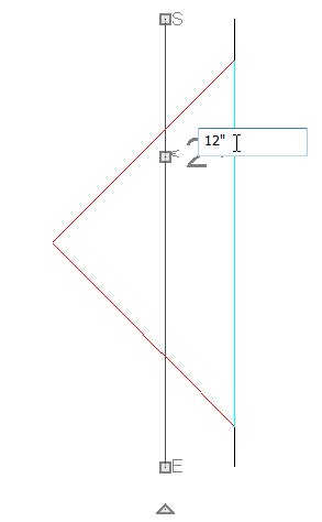
- In this example, 12" is used.
- Select Build> Wall> Straight Exterior Wall
 and draw a wall that snaps to the second CAD line.
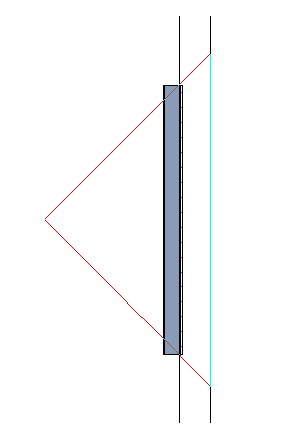
- If the current floor is the Attic, a message will confirm whether you really want to draw on this floor. Click OK.
- With the wall still selected, click the Open Object
 edit button and on the GENERAL panel of the Wall Specification dialog, check the box beside Attic Wall and click OK.
- Go Down One Floor
 , click the Select Objects
  button, and select the roof plane located below the gable that you wish to create.
- Click the Break Line
 edit tool to add a new corner edit handle at the point where the selected roof plane meets the intersection of one of the topmost roof planes and the roof beneath it.
- Click and drag the corner edit handle located at the selected roof plane's peak and drag it down until it snaps to the roof plane intersection located on the opposite edge as the newly created corner.
- Adjust the position of the roof plane's topmost edge so it snaps to the wall in the Reference Display.
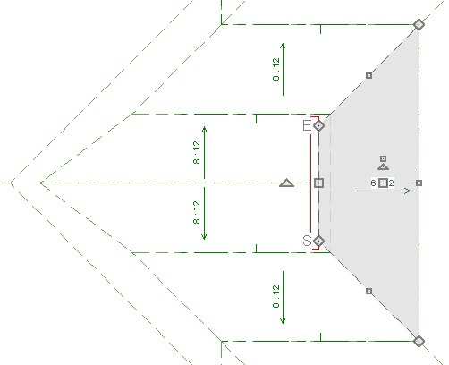
- Create a Perspective Overview
 to see the results.
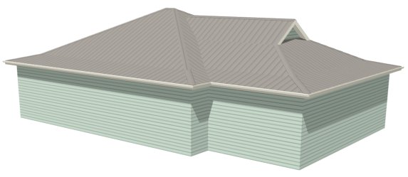


 from the menu.
 from the menu, then click and drag a rectangular selection marquee around the structure to select all of the exterior walls at once.
 edit button, and on the ROOF panel of the Wall Specification dialog:
 dialog once more by going to Build> Roof> Build Roof, check Build Roof Planes, and click OK.
 from the menu to see the results so far. Close
  the overview and return to floor plan view when you are finished.
 from the menu, then click and drag a camera arrow that begins in front of the structure and ends just past the roof ridge.
 from the menu, then click and drag to draw a CAD line snapped to the ridge of the roof where a third pitch will be added.
 below and parallel to the first one. Make sure it extends into the roof plane.
 from the menu, then click and drag a dimension line between the two CAD lines.
 button, then click on the roof plane to select it. Use the resize edit handle on the top edge to drag it downward until it snaps to the lower CAD line.
 to return to floor plan view without closing the elevation view.
 from the menu, then draw a roof plane adjacent to the ridge edge of the roof plane that you just modified. To do this:
 edit button to open the Roof Plane Specification dialog, and on the ROOF panel, make sure that the Baseline Height is locked and then change the Pitch to 8 in 12.
 to see the results so far. Close
  the view when you are finished.
 the new roof plane.
  as described above.
 the elevation view without saving it.
 edit button.
 edit tool to join the topmost roof plane with the roof plane adjacent to its side. To do this:
 edit button.
 edit button.
 edit button, then move your mouse pointer over the topmost roof plane's ridge line.
 and turn on the Reference Display
  . Notice that the portion of the roof that the topmost roof planes overlap is represented by a triangle.
 from the menu, then:
 and draw a wall that snaps to the second CAD line.
 edit button and on the GENERAL panel of the Wall Specification dialog, check the box beside Attic Wall and click OK.
 , click the Select Objects
  button, and select the roof plane located below the gable that you wish to create.
 edit tool to add a new corner edit handle at the point where the selected roof plane meets the intersection of one of the topmost roof planes and the roof beneath it.
 to see the results.