This article also applies to the following legacy products:
Pro
QUESTION
How can I have Chief Architect create a cricket in my roof plan?

ANSWER
Roof crickets, sometimes called saddles, are raised roof planes built to divert water or snow. When a roof is generated automatically, crickets will not be produced, but they can be drawn manually using the Roof Plane tool. Dormer vents can be created using a similar technique.
To create a manually drawn chimney cricket
-
Create a basic rectangular structure with a hip roof and a chimney following KB-00058 Creating a Custom Chimney and Fireplace found in the Related Articles section below.
- In this example, the display of Roof Plane Labels is turned off
-
Make any required changes to the fireplace.
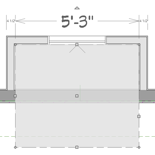
- In this example, a soffit 63" wide is used for the fireplace chimney.
-
Select Build> Roof> Build Roof
 from the menu, and in the Build Roof dialog, specify the Pitch, Framing, and any other attributes that you will need for the cricket.
- In this example, a Pitch of 12:12 and 1 1/2" x 5 1/2" rafters are specified.
- Do not check Build Roof Planes. Here, the Build Roof dialog is being used to set the defaults for manually drawn roof planes.
-
Select Build> Roof> Roof Plane from the menu, then:
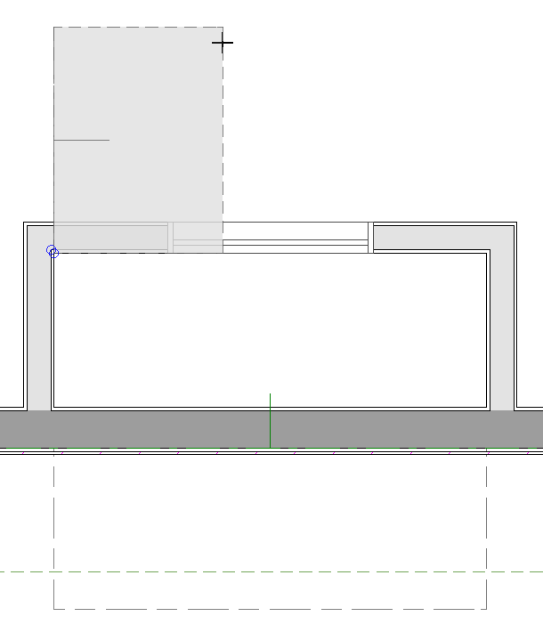
- Click on the edge of the soffit near one of its endpoints and drag to draw a roof baseline perpendicular to the exterior wall, towards the structure’s interior.
- Release the mouse button and move the mouse parallel to the soffit edge and in the direction of the fireplace’s center and click once.
- The roof plane that is created will draw its height from the top of the roof below at the point where you first clicked to begin drawing.
-
Use dimensions to resize the new roof plane so that it measures half the width of the fireplace from its low edge to its ridge.
- In this example, that distance is 31 1/2".
-
Use Roof Intersection Points to find the intersection point for the edge of the roof plane opposite the fireplace.
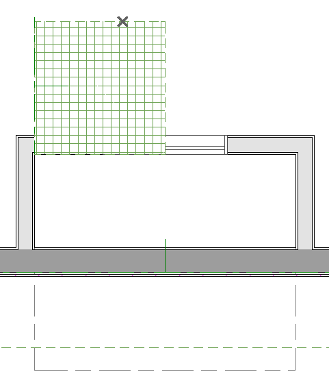
- If the program creates an Intersection Point that is not located on the roof plane edge, move that edge so that it is closer to the fireplace and the roof plane is more narrow and try again.
-
Use the roof plane’s edit handles to:
- Angle the low edge of the roof plane up to the Intersection Point.
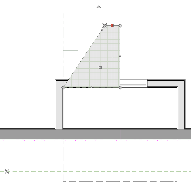
- Drag the short edge of the roof plane outward until it disappears and the roof plane becomes a triangle.

-
Use the Copy/Paste
 edit tool in combination with the Reflect About Object
  edit tool to create a copy of the cricket roof plane.
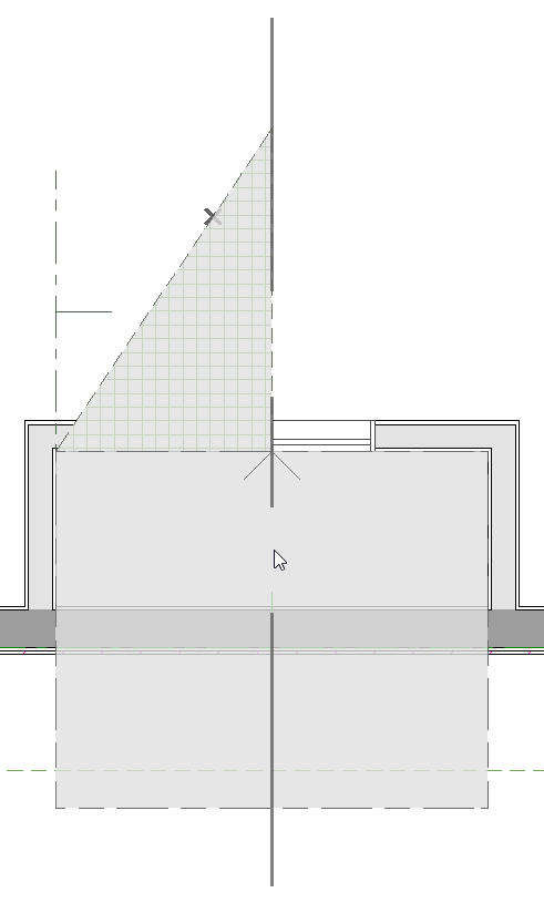
- Copy/reflect the roof plane about the fireplace to produce a roof plane that slopes in the opposite direction as the original.

-
Create a 3D view to see the results.
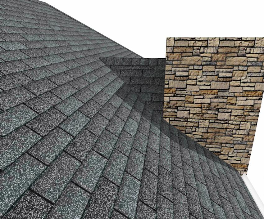
Remember to restore the settings in the Build Roof dialog if you intend to draw more structural roof planes in your plan.
The cricket created above can easily be converted into a dormer vent. Begin by closing the 3D view and returning to floor plan view.
To create a dormer vent
-
Select the soffit/chimney positioned in front of the cricket and click the Delete
 button.
-
Go Up One Floor
 and select Tools> Floor/Reference Display> Reference Display
  .
.
In Chief Architect X10, Home Designer Pro 2019, and prior program versions, navigate to Tools> Reference Floors> Reference Floor Display  instead.
-
Select Build> Wall> Exterior Wall
 and draw a wall inside the area of the roof cricket on the floor below, parallel to its front.
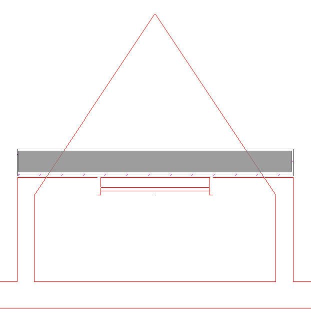
If you draw the wall in the wrong direction and its siding layer faces the interior, select it and click the Reverse Layers  edit button.
-
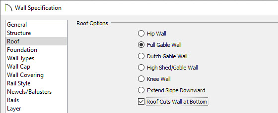
Click on the wall to select it and click the Open Object
 edit button. On the Roof panel of the Wall Specification dialog, check the box beside Roof Cuts Wall at Bottom and click OK.
-
With the wall still selected, use its edit handles to move it the desired distance from the eaves of the roof cricket.
-
Create a 3D view to see the results.
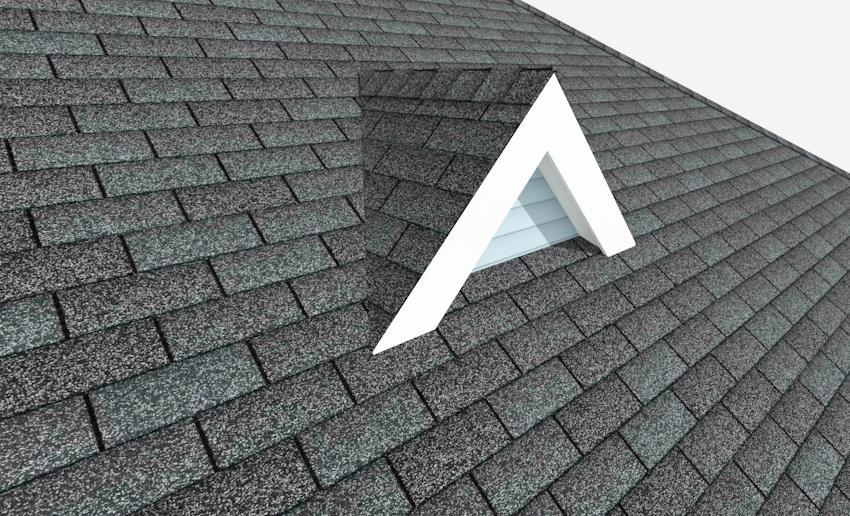
-
A selection of attic vents is available in the Library Browser.


