The information in this article applies to:

QUESTION
How can I create hip and gable roofs using the manual roof tools?
ANSWER
Chief Architect allows you to create a wide variety of roof styles automatically. However, in some situations it might be more convenient to create roofs manually. In this tutorial, we will show you how to set up your roof defaults, as well as how to draw roof planes manually to create both a hip and gable roof.
To set up your roof defaults
- In a New Plan
 , navigate to Edit> Default Settings
  .
.
- In the Default Settings dialog, select Roof, then click Edit.
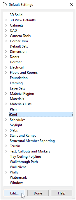
- In the Roof Defaults dialog that displays next:
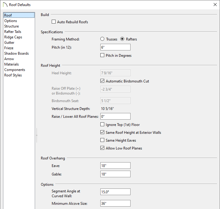
- On the General panel, uncheck Auto Rebuild Roofs to disable the automatic roof generation functionality, then set the desired Framing Method, Pitch (in 12), as well as any other Roof Height and Roof Overhang settings.
In this example, the Pitch (in 12) value of 6" is used, and is the only setting that has been changed from the default.
- On the Options panel, specify your desired Eave, Ceiling Break Lines, and Supply settings.
- Navigate through each of the remaining panels, one-by-one, and continue specifying the roof settings to your liking.
- When you are finished, Click OK and Done to confirm your changes and close the dialogs.
To create a hip roof manually
- Select Build> Wall> Straight Exterior Wall
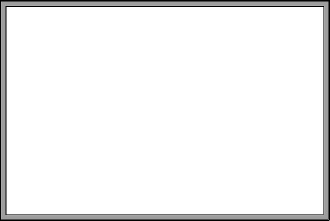
 from the menu and draw four connecting walls to form an enclosed area.
In this example, a simple rectangle is drawn.
- Select Build> Roof> Roof Plane
 from the menu.
- Starting on the left hand side of the plan, click and drag a baseline down along the outside surface of the wall's framing layer.
- When Object Snaps
 are enabled, the program will snap the roof planes baseline to that point automatically.
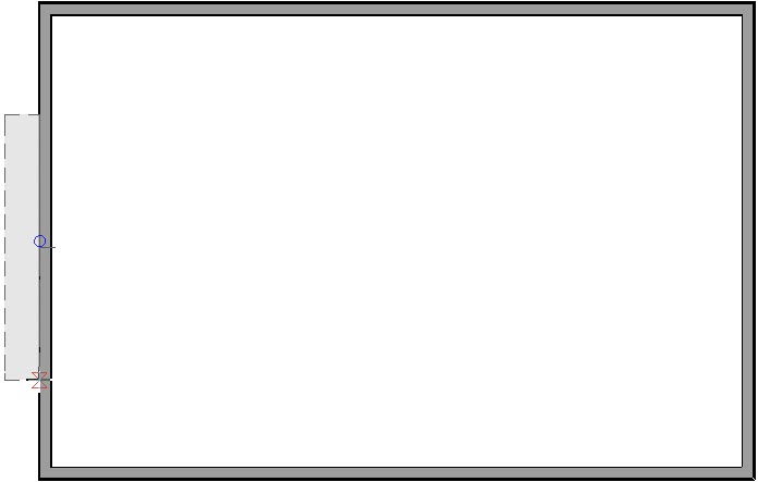
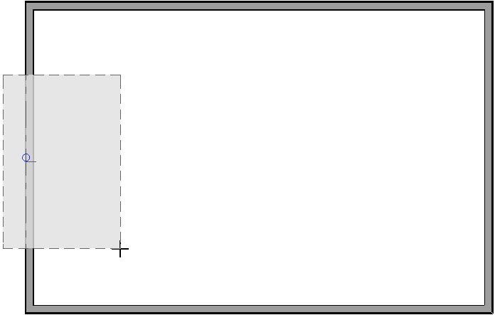
- Release the mouse button and then click inside the room to identify the location of the ridge and to create a roof plane.
- Repeat this process on the three remaining sides of the building.
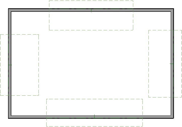
- Click on the upper roof plane along its right hand side to select it. Notice that the edit handle that displays on the edge that you clicked on is bigger than the edit handles on the other 3 edges, indicating that it's the selected edge.
- Click the Join Roof Planes
 edit button.
- As you hover over the edge of another roof plane, a preview displays showing you how the roof planes will join. Click once to join the two edges together.
- Repeat this process to join the adjacent edges of the remaining roof planes.
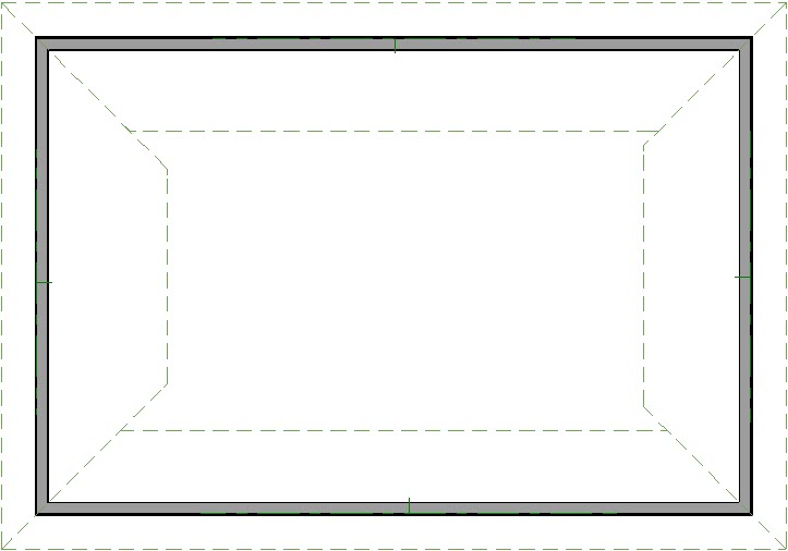
- Click on the ridge edge of the upper roof plane to select it.
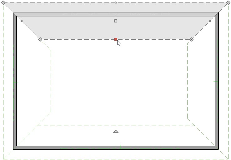
- Click the Join Roof Planes
 edit button.
- Click the ridge of the lower roof plane to join them together.
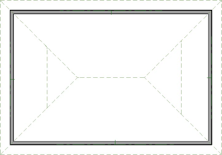
- Click on the ridge of the roof plane on the right side of the plan.
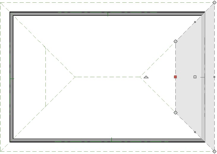
- Click the Join Roof Planes
 edit button.
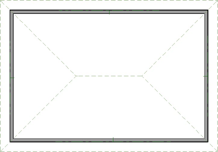
- Click on the right edge of the upper roof plane.
- Repeat this process for the roof plane on the left side of the building.
To create a gable roof manually
- Select Build> Wall> Straight Exterior Wall
 and draw four connecting walls to form an enclosed area.
Again, a simple rectangle is used in this example.
- Follow the steps described in step 2, above, to create two roof planes on opposite sides of the building.
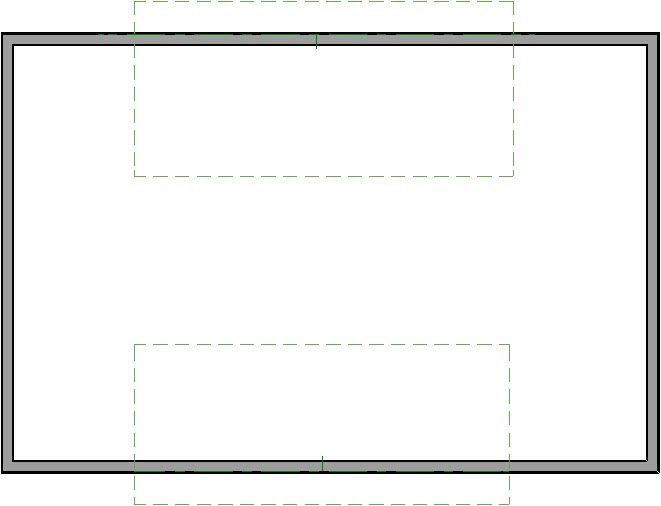
- Click on the ridge edge of the lower roof plane to select it.
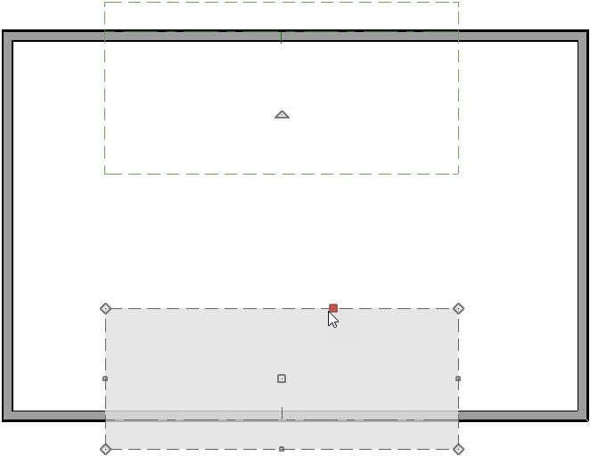
- Click the Join Roof Planes
 edit button.
- Click the ridge edge of the upper roof plane to join the two together.
- Select the View menu and make sure that there is a check beside Temporary Dimensions
 . If there is not, click on this menu item to turn on the display of Temporary Dimensions.
- Click on the right side of the upper roof plane to select it.
- Left-click on the temporary dimension between the roof plane edge and the wall.
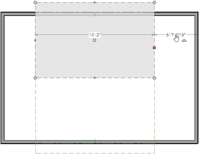
- In the text box, type a distance value of -18". The 18 represents the desired gable overhang.
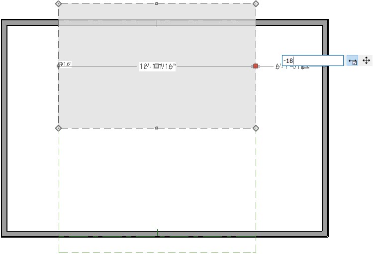
- In this example, it's important that a negative number be used. This directs the program to move the roof plane edge to the opposite side of the wall, rather than keeping it on the same side.
- Repeat for the left edge of the upper roof plane.
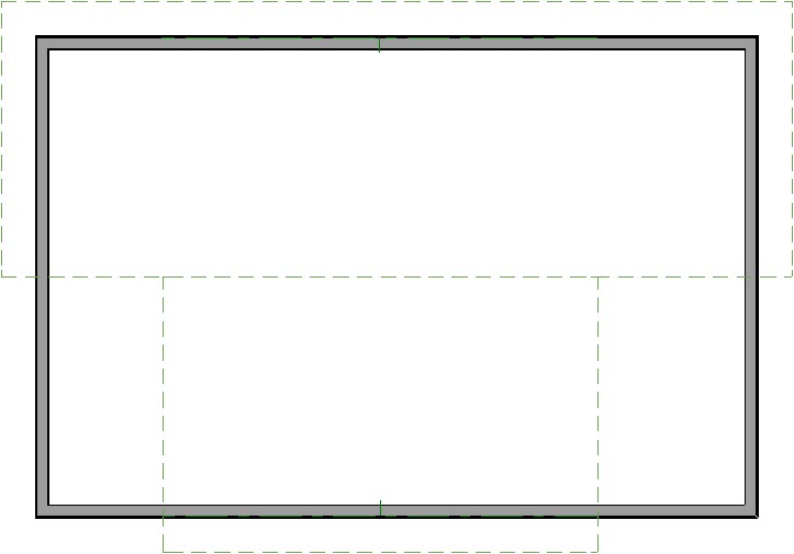
- With Object Snaps
 enabled, drag the left and right sides of the bottom roof plane so that they snap to the respective sides of the upper roof plane. As you drag each edge outward, move your cursor towards the side edge of the upper roof plane. The program will locate the edge and snap the currently selected edge to it.
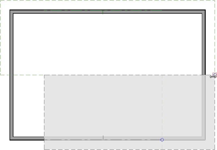
- Repeat for the opposite side.
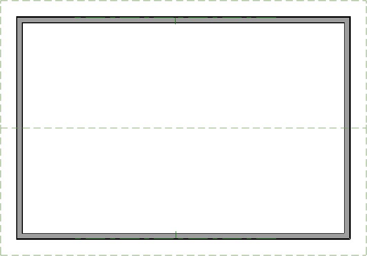


 from the menu and draw four connecting walls to form an enclosed area.
 from the menu.


 edit button.

 edit button.

 edit button.
 and draw four connecting walls to form an enclosed area.

 edit button.


