QUESTION
When I select Build> Electrical from the menu, I see Outlet tools, a Light tool, a Switch tool, a Rope Light tool, and an Electrical Connection tool. How do I add special application outlets and switches, light fixtures with different styles, other objects such as smoke detectors and fans, as well as show how they are connected?
ANSWER
A wide variety of electrical objects, such as cable and telephone jacks, doorbells, thermostats and intercoms are available in the Library Browser to place in your plans. You can also specify which electrical objects are placed when you use the Electrical tools mentioned above. Lastly, you're able to show how these objects connect to each other by using the Connect Electrical tool.
To place electrical objects from the library
- From the menu, select View> Library Browser
 to open the Library Browser if it's not already open.
- Browse to Chief Architect Core Catalogs> Architectural> Lighting to find additional light fixtures, or browse to Chief Architect Core Catalogs> Mechanical, Electrical, Plumbing> Electrical to find other types of electrical objects.
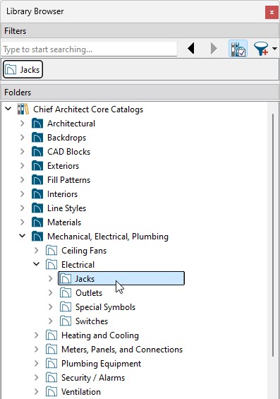
- Once you have found an object you'd like to place, click on it within the library to select it.
- When you move your cursor into the drawing area, it will display the Electrical icon
 .
.
- Click once in the drawing area to place the selected electrical object at your desired location.
To set electrical tool defaults
- Select Edit> Default Settings
 from the menu.
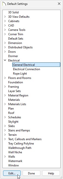
- In the Default Settings dialog, expand the Electrical option, select General Electrical, then click Edit.
- In the Electrical Defaults dialog:
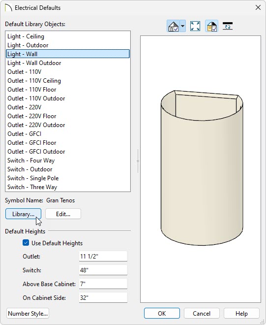
- Using the Default Library Objects list, click on the type of electrical object that you want to set a default electrical object for.
Notice that there are varying default options for lights, outlets, and switches, depending on the location they're originally placed at in your plan. For example, if you click along a wall while the Light  tool is selected, it will place whatever object is specified for the Light - Wall option.
- Click the Library button to browse the library for an object that suits your needs. Once a desired object has been selected click OK. To make further adjustments to a selected object, click the Edit button.
- Make any needed changes to the Default Heights of outlets and switches. When the Use Default Heights box is unchecked, electrical objects use the height saved with their symbol.
- When you are satisfied with your selections, click OK to close the dialog and apply your changes.
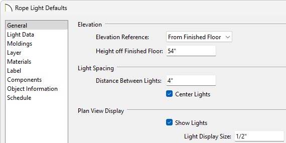
- Staying within the Default Settings dialog, select the Rope Light option, then click Edit.
- In the Rope Light Defaults dialog, specify your desired properties.
- Once all desired changes have been made, click OK and Done to close the dialogs.
- Select Build> Electrical
 from the menu and choose an electrical tool.
- With the tool selected, click once in your plan to place the electrical object at that location.
If you're using the Rope Light  tool, click and drag instead.
To connect electrical objects
- In X16 and newer you will first want to configure your electrical connection defaults to your preference by selecting Edit> Default Settings from the menu.
In X15 and prior versions, skip to Step 3.
- In the Default Settings dialog, expand the Electrical option, select Electrical Connection, then click Edit
- On the spline panel you can adjust the New Segment Angle and the Curvature Ratio defaults.
- On the line style panel you can adjust the Layer, Color, Style, Weight, and Drawing Group of the electrical connections.
- On the label panel you can modify the default label for your electrical connections.
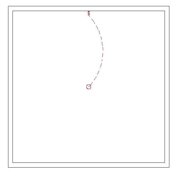
- Once you have your electrical objects placed and your electrical connection defaults* are configured, navigate to Build> Electrical> Electrical Connection
 , then click and drag between electrical objects to create an electrical connection simulating an electrical circuit.
*Applies to X16 and newer versions.
Typically you will want to draw these connections for objects such as switches, outlets, lights, ceiling fans, and other electrical objects.