The information in this article applies to:

QUESTION
I need to draw a window well for an egress into my design. How do I do this?

ANSWER
In this article, we will walk through the steps to create an opening in your terrain for an egress window. This article assumes that you have already created a foundation level, or Floor 0 in your plan, and have an existing Terrain Perimeter created on Floor 1.
It is important to check the code regulations for your particular area on the necessary dimensions for the window and egress opening.
To create an egress
- Access your desired plan, then navigate down to Floor 0
 .
.
- Navigate to Build> Wall> Straight Exterior Wall
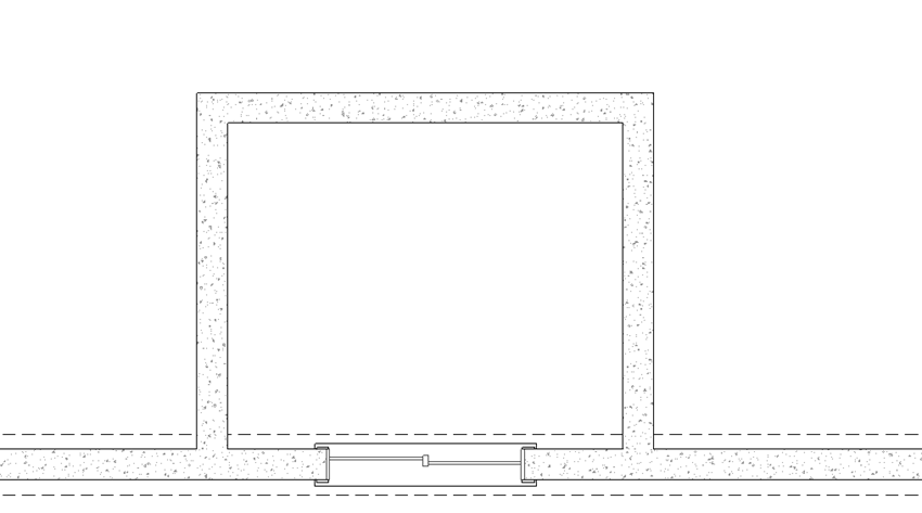
 , then click-and-drag to draw the walls for the window well.
For the purposes of this article, we used the 8" Concrete Stem Wall wall type to create the window well.
You may want to create a custom wall type for your window well instead. More information on creating and changing wall types can be found in the Related Articles section below.

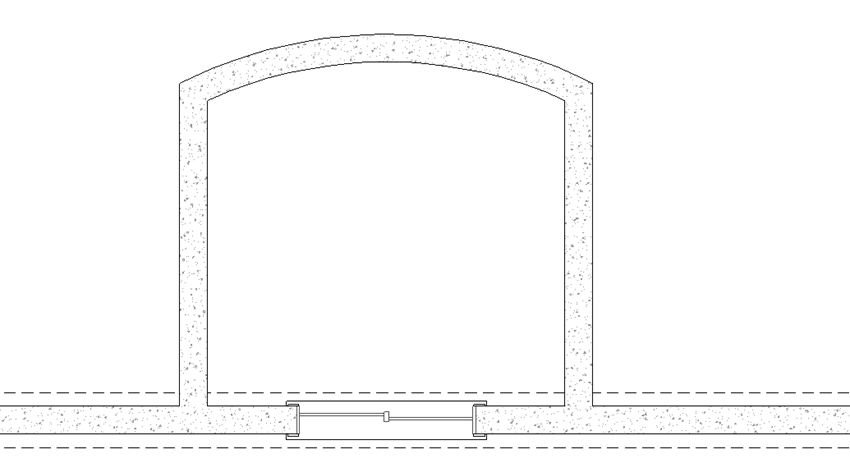
- Since the egress in our example has a slightly curved outer wall, we will click on the outer wall to select it, then click on the Change Line/Arc
 tool to change it to a curved wall.
We could have also used the Curved Wall  tool to place a curved wall here initially.

- Using the Select Objects
 tool, click inside the newly created egress area and choose the Open Object
  edit tool.
- In the Room Specification dialog that displays:
- On the General panel, specify a custom Room Name of "Egress".
- On the Structure panel, set the desired Floor value, then uncheck the Roof Over This Room box.
In this example, a value of -72 5/8" is specified.
- Check the Floor Under This Room box if it's not already checked, then and specify your Floor Finish and/or Floor Structure, if needed.
A window well or egress window will typically have either concrete with a drain or gravel for drainage purposes.
- When you are finished, click OK to close the dialog and apply your changes.
- Next, navigate to Floor 1
 and select Tools> Floor/Reference Display> Reference Display
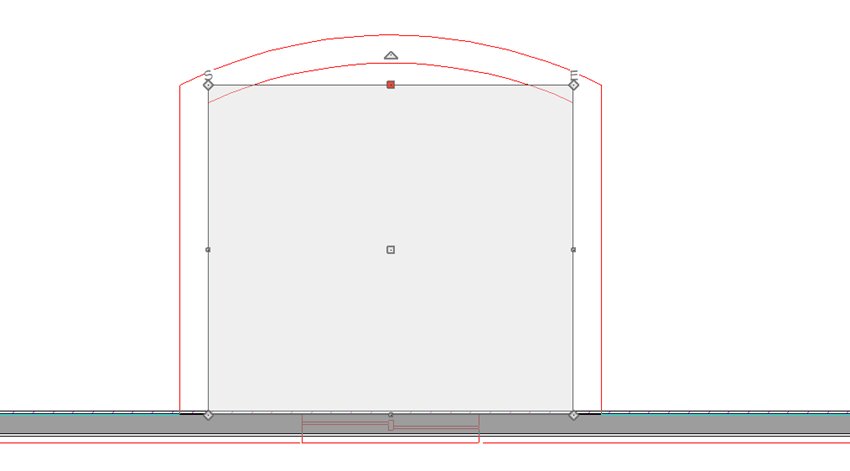
  to turn on the Reference Display, which allows you to see where the walls on the Foundation level were placed.
- Select Terrain> Feature> Terrain Hole
 and, using the red outline of the walls on the foundation level as a guide, click-and-drag to draw a rectangular terrain hole aligned with the inside of the foundation walls below.

- Once placed, select the side of the terrain hole that corresponds with the curved wall beneath it, then click on the Change Line/Arc
 edit tool.
The terrain hole can be adjusted further, if necessary, to fit inside of the walls referenced on Floor 0, using its edit handles.
- Add some steps, a ladder, or handholds that will allow the egress to be used for its functional purpose. You may find it helpful to first place them in plan view, then move them into place in a 3D camera view.
You can download and install the Exterior Egress Bonus Catalog from the Chief Architect 3D Library for additional accessories.


 tool to change it to a curved wall.
  tool to place a curved wall here initially.
 tool, click inside the newly created egress area and choose the Open Object
  edit tool.
 to turn on the Reference Display, which allows you to see where the walls on the Foundation level were placed.
 and, using the red outline of the walls on the foundation level as a guide, click-and-drag to draw a rectangular terrain hole aligned with the inside of the foundation walls below.
 edit tool.