The information in this article applies to:

QUESTION
How can I create new wall types?
ANSWER
Chief Architect has a variety of wall types that you can readily use in any of your plans. You also have the ability to create your own custom wall type using the Wall Type Definitions dialog.
To create a new wall type
- Navigate to Build> Wall> Define Wall Types
 .
.
This dialog can also be accessed by clicking the Define button on the Wall Types panel of the Wall Specification dialog or in the Wall Defaults dialog.
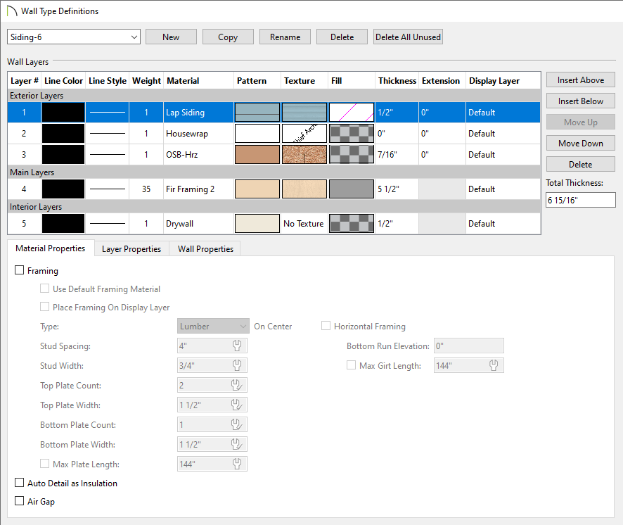
- In the Wall Type Definitions dialog:
- Click the New button at the top of the dialog.
Depending on the new wall type you wish to create, you may be able to save time by selecting a similar preexisting wall type from the drop-down list at the top of the Wall Type Definitions dialog. A preview diagram of the selected wall type appears in the dialog. With the similar wall type selected, click the Copy button at the top of the dialog. You may also wish to rename this copy.
- Replace the wall type name with a short, descriptive name.
- To the right of the Wall Layers table, click the Insert Above or Insert Below button to add a new layer to your wall. This new layer is placed above or below the currently selected wall layer respectively.
You can select a wall layer and click Move Up or Move Down to rearrange the wall layers, or you can click the Delete button to remove a layer entirely.
- Repeat Step 3 to add as many layers as needed.
- In the Wall Layers table:
- Click on a selected layers' Line Color and/or Weight column to change the line color and line weight.
- Click on a selected layers' Material, Pattern, and/or Texture column to open the Select Material dialog, where materials and their properties can be specified.
- You can specify the desired fill style for a wall layer by selecting a particular wall layer and clicking its Fill column.
- Specify the Thickness of each wall layer.
- In X15 and newer, an Extension column is available, allowing you to set how far the selected layer extends past its default bottom elevation, either at the bottom of the wall's bottom plate or that of the floor platform it builds on. This setting is only available for layers located in the Exterior Layers section of the table. You can also specify a negative value if you would rather have the layer stop short of the bottom elevation.
- In X16 and newer, a Display Layer column is available for each layer, allowing you to manually specify the display layer that each wall layer is placed onto. For more information on layers, please see the "Understanding Layers" resource in the Related Articles section.
-
On the
Material Properties tab in X15 and newer, or under the Material Layer section in X14 and prior, specify whether the selected wall layer is marked as
Framing,
Auto Detail as Insulation, and/or
Air Gap.
- Check Framing to produce framing for the selected layer when wall framing is generated. Select the appropriate framing Type from the drop-down menu, the Stud Spacing, as well as the Stud Width.
- Set your Top and Bottom Plate Count and Width, as well as the Max Plate Length.
- Check Horizontal Framing to produce framing that runs horizontally instead of vertically, sometimes referred to as girts. When this is checked, specify the Bottom Run Elevation, which is measured from the center of the lowest horizontal framing member relative to zero, the default top height of the subflooring on Floor 1. Also, specify the Max Girt Length, available in X14 and newer versions.
- Check Auto Detail as Insulation to generate Insulation boxes in the selected layer when Auto Detail is used in cross section views.
- Check Air Gap to prevent the selected layer from displaying in 3D views or being calculated in the Materials List.
- On the Layer Properties tab in X15 and newer, or under the Selected Wall Layer Line section in X14 and prior, specify the Display Layer*, Line Color, Line Weight, Line Style, and Extend Layer (Extension)** of a selected wall layer. Most of these properties can also be changed using the Wall Layers table mentioned in Step 5 above.
*Applies to X16 and newer.
**Applies to X15 and newer.
- On the Wall Properties tab in X15 and newer, or under the Energy Values section in X14 and prior, specify the wall type’s Energy Values. This information is used when exporting to REScheck.
- On the Wall Properties tab in X15 and newer, or under the Wall Settings section in X14 and prior, specify additional properties related to the wall type.
- Specify the Brick Ledge Depth, which is the vertical depth of the brick ledge under walls of this type when a Brick material Type is specified for the exterior layer and a monolithic slab foundation is built.
- Use the Build Platform to Exterior of Layer drop-down menu to select the wall layer whose exterior you would like the program to build the floor platform to. If this setting is set to the exterior wall layer, no exterior material will generate to cover the floor platform.
- Repeat this process for Dimension to Exterior of Layer and Foundation to Exterior Layer to choose which layer you want dimension lines to locate and which layer you would like the foundation built to respectively.
- Specify a Foundation Offset value to offset the Main Layer of a foundation wall on the floor below relative to the Foundation to Exterior of Layer setting. A positive value offsets toward the exterior; a negative value offsets toward the interior.
- Check Partition Wall to prevent walls of this type from cutting through the surface layers of floors, ceilings, and other walls.
- When you have completed your new wall type, click OK to close the dialog.
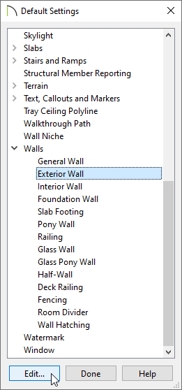
To set the new wall type as the default
- Select Edit> Default Settings
 , and in the dialog that displays, expand the Walls category.
- Select Exterior Wall, Interior Wall, or the type of wall you wish to change the default wall type for, then click Edit.
- On the Wall Types panel of the Exterior Wall Defaults, Interior Wall Defaults, or other defaults dialog, click the Wall Type drop-down menu to choose your new wall type.
- Click OK and Done.
- Now, any new walls that you create in this plan will use your new wall type.
You can also change the wall type for walls that already exist in your plan. To learn more, please see the Related Articles section below.