The information in this article applies to:

QUESTION
I need to create a flared skylight shaft. How can I do this?
ANSWER
The settings in the Roof Hole/Skylight Specification dialog allow you to control how the roof hole is cut through the roof plane, but not how it builds down to the ceiling below. If you need the skylight shaft to be flared, you can accomplish this by displaying and editing the ceiling platform hole associated with the skylight shaft.
To create a flared skylight shaft
-
Open
 the plan in which you wish to create a flared skylight shaft.
- Select Build> Roof> Skylight
 from the menu, then either:
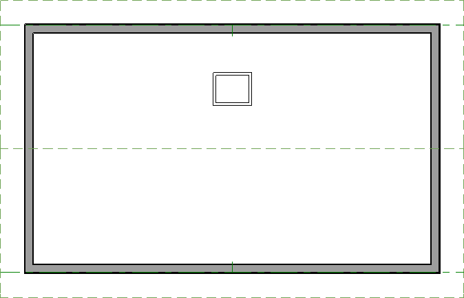
- Click and drag within a single roof plane to draw a skylight; or,
- Click once to place a 2' x 2' (600 mm x 600 mm) square skylight.
In X15 and newer versions, Skylight defaults are available, which can be accessed by navigating to Edit> Default Settings.
Additionally, a skylight will display a projected size when inserted into a sloped roof plane instead of its true size. To see and edit the true size of a skylight in X15 and newer versions, select the skylight and open it to specification or click on the Edit Skylight Shape edit tool.
- Using the Select Objects
 tool, click on the skylight to select it, then click the Open Object
  edit button.
- On the General panel of the Roof Hole/Skylight Specification dialog that displays:
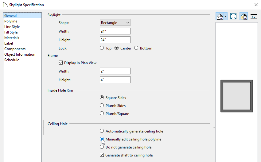
- Specify the desired Inside Hole Rim option, which is the angle that the skylight is cut into the roof plane. Choose Square Sides for cuts that are perpendicular to the roof pitch, Plumb Sides that are vertical, or Plumb/Square for a plumb cut on the lower end of the skylight and a square cut on the higher end.
- Select the Manually edit ceiling hole polyline option under the Ceiling Hole section.
- Click OK to close the dialog and apply your changes.
Notice that there are now two polylines at the location of the skylight - one for the skylight itself, and a second one for the ceiling hole polyline.

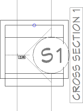
- Select 3D> Create Orthographic View> Backclipped Cross Section
 from the menu, then click and drag a camera arrow that both begins and ends inside the skylight.
- In the section view, select CAD> Lines> Draw Line
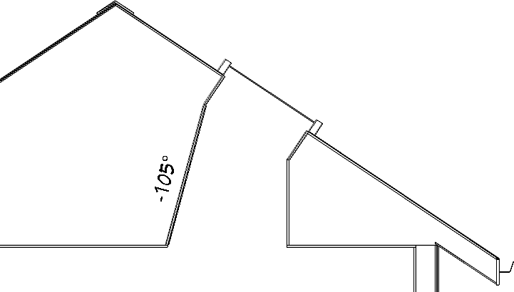
 from the menu, then click and drag a line representing the desired angle of the skylight well.
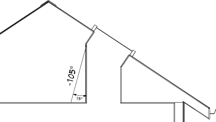
- If a specific angle is needed, you can type it in the Line Specification dialog.
In this example, the CAD line is set to have an angle of -105°.
- Select Window> Tile Vertically
 to tile your floor plan view and cross section view windows next to one another. Click in the floor plan view window to activate it, then using the Select Objects
  tool, click on the ceiling hole polyline to select it.
- Use the ceiling hole polyline's edit handles to extend it in the appropriate direction, then release the edit handle to see the results in the cross section view.
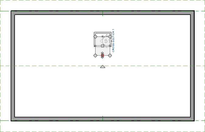
- Continue adjusting the ceiling hole until the edge of the skylight shaft meets up with the CAD line.
Skylights must always be contained by a single roof plane. If the roof plane is deleted, any skylights or holes it contains are also deleted.


