QUESTION
How do I create a vaulted ceiling and scissor trusses?

ANSWER
In Chief Architect, roof trusses are generated in the space between roof planes and ceiling planes. When a vaulted ceiling has a different pitch than the roof planes above, scissor trusses are produced.
To build the structure and roof
- Access the file in which you would like to create scissor trusses within.
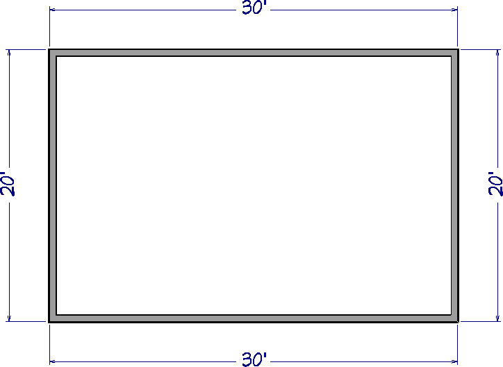
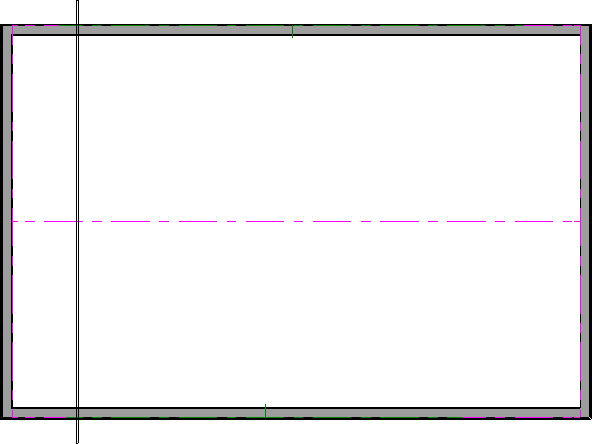
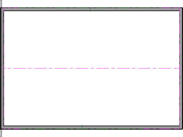
In this example, we will be creating scissor trusses within a simple 20' x 30' rectangular structure.
- Using the Select Objects
 tool, select the walls that you would like to make gable walls, then click the Open Object
  edit button.
In this example, the left and right walls were selected and opened.
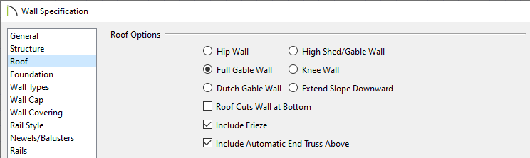
- On the Roof panel of the Wall Specification dialog, select the Full Gable Wall option and click OK.
- Select Build> Roof> Build Roof
 and on the Roof panel of the Build Roof dialog that displays:
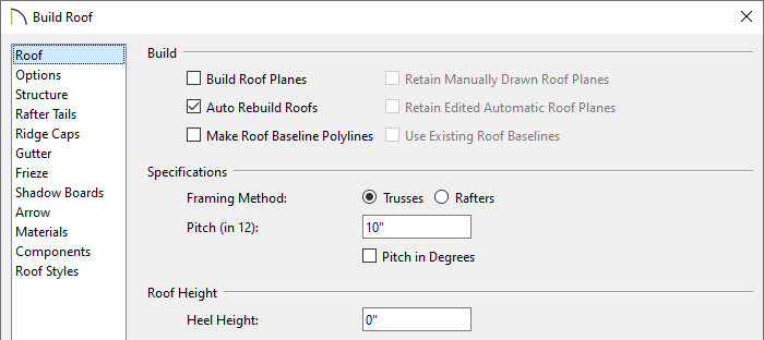
- Check Auto Rebuild Roofs if it's not already checked.
- Select the Trusses Framing Method.
In X14, Home Designer Pro 2023, and prior versions, check the Trusses (no Birdsmouth) box instead.
- Set the desired Pitch (in 12).
In this example, a 10" in 12 pitch is used.
- Set the Heel Height to your liking.
In X14, Home Designer Pro 2023, and prior versions, you must uncheck Automatic Birdsmouth Cut to define a raised heel.
In this example, the value of 0" is used.
- Click OK to build the roof.
To build the ceiling
- Using the Select Objects tool, click in the room that will have a vaulted ceiling to select it, then click the Open Object edit button.
- On the Structure panel of the Room Specification dialog, uncheck Flat Ceiling Over This Room, then click OK.
- To make it easier to draw ceiling planes, select Tools> Layer Settings> Display Options
 and in the Layer Display Options dialog for the active layer set:
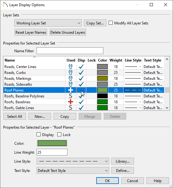
- Scroll down to the "Roof Planes" layer and remove the check in the Disp column or from the Display checkbox.
- Click OK to close the dialog and turn off the display of the roof planes in the plan.
- Select Build> Roof> Ceiling Plane
 from the menu.
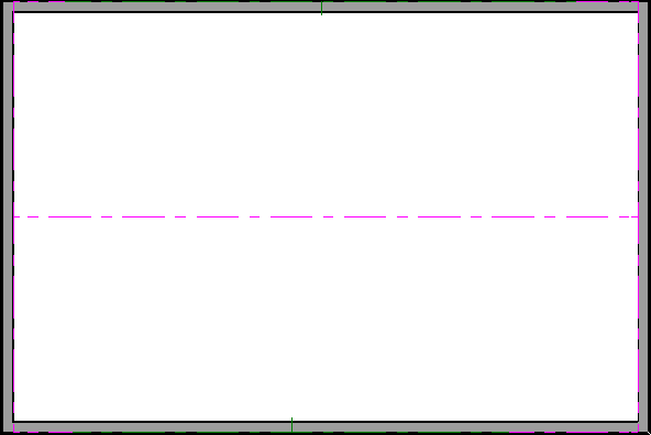
- Click and drag a baseline along the outside of a wall defining the room that will have a vaulted ceiling.
- When the baseline is complete, click once in the room to set the ceiling planes ridge.
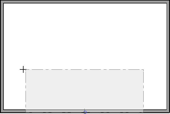
- Click on the ceiling plane to select it, then use the edit handles that display to stretch it across the room to the inside surfaces of the gable walls.
In this example, two ceiling planes will form a ridge in the center of the room, so make sure the ridge edge of this plane does not extend past the middle of the room.

- With the ceiling plane still selected, click the Open Object edit button and on the General panel of the Ceiling Plane Specification dialog:
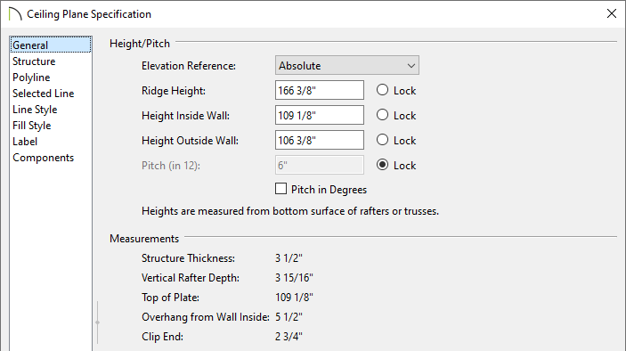
- Specify the desired Pitch for your vaulted ceiling.
In this example, 6" in 12 is used.
- Now lock the Pitch and set the Height Inside Wall value to match the Top of Plate value.
- Click OK to close the dialog and apply the change.
- Repeat steps 4 through 6 to create a second ceiling plane opposite the first one.
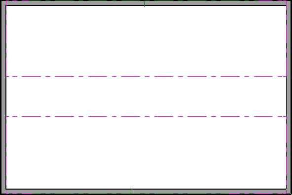
- Click on the ridge edge of one of the ceiling planes,
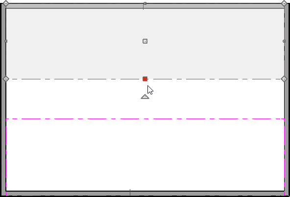
- Click the Join Roof Planes
 edit button then click the ridge edge of the other ceiling plane.
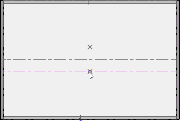
- The two ceiling planes will join along the selected edges.
If you wish, you can now turn the display of roof planes back using the Layer Display Options dialog or Active Layer Display Options side window.
With both the ceiling and roof planes in place, you can now create roof trusses.
To create scissor trusses automatically*
*Applies to Chief Architect Premier X15, Home Designer Pro 2024, and newer versions.
- Select Build> Framing> Build Framing
 from the menu.
- In the Build Framing dialog that appears, click on the Framing Defaults button.
In X15 and Home Designer Pro 2024, skip this step and proceed to Step 3.
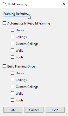
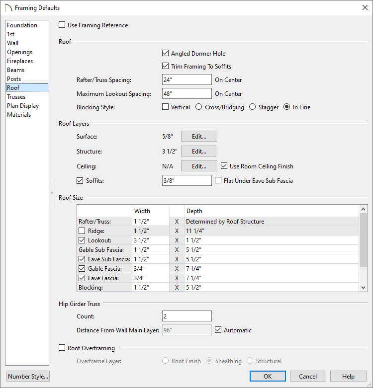
- Access both the Roof and Trusses panels in the dialog that appears, and verify that the settings are set to your liking.
- Once your roof framing settings are setup to your liking, click OK, check the appropriate Roofs box in the Build Framing dialog, then click OK.
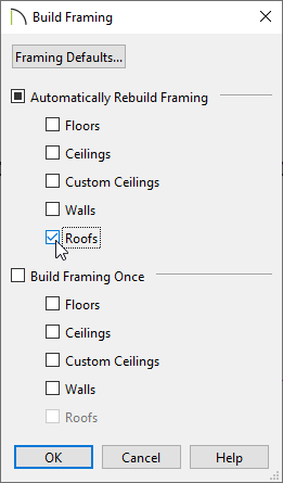
In X15 and Home Designer Pro 2024, check the Build Roof Framing or Automatically Build Roof Framing box located on the Roof panel of the Build Framing dialog instead, then click OK.

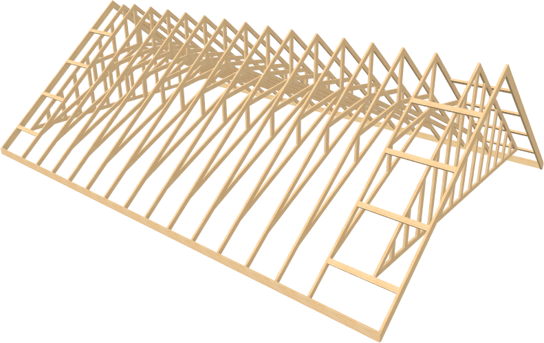
Automatic trusses, along with any other automatic framing components, such as blocking and fascia boards, will be generated.
You may also be prompted to choose whether or not to display roof framing layers in the active view. Whichever choice you choose will not affect the generation of the framing components.
The trusses located on each end of the structure will be reduced gable end trusses. If you don't want these types of trusses to be built automatically, open the two gable walls up to specification, select the Roof panel, and uncheck the "Include Automatic End Truss Above" box. Once you regenerate the roof framing, end trusses will no longer be built.
- Create a Perspective Framing Overview
 to see the results.
To create scissor trusses manually
- Select Build> Framing> Roof Truss
 from the menu.
- Click and drag to draw a roof truss perpendicular to the ridge line of the roof and ceiling planes.
- Click on the truss to select it and move it so that the exterior edge of the truss is aligned with the exterior edge of the framing layer of the wall.
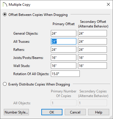
- With the truss still selected, click the Multiple Copy
 edit button, then click the Multiple Copy Interval
  button to open the Multiple Copy dialog. Verify that Offset Between Copies When Dragging is selected and that the Primary Offset specified for All Trusses equals the desired O.C. truss spacing, then click OK.
In this example, the default Primary Offset value of 24" is used.
- Hover over the main Move edit handle on the truss until you see the Multiple Copy
 cursor display, then click and drag across the structure to create copies 24" apart.
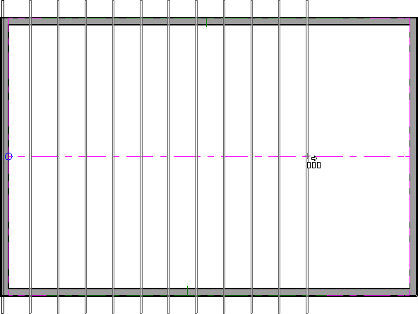
The trusses located on each end of the structure will be full size trusses. If you wish to have end trusses instead, select the trusses on each end, open them up to specification, check the "End Truss" and "Force Truss Rebuild" boxes, then click OK.
- Create a Perspective Framing Overview to see the results.
Now, additional framing components, such as lookouts and fascia boards, can be generated automatically using the Build Framing dialog.


