The information in this article applies to:

QUESTION
I need to create a clerestory. How do I do this?

ANSWER
A clerestory typically consists of a wall built above part of the roof with high windows to let in light. A clerestory can be easily created using the Roof Cuts Wall at Bottom setting in the Wall Specification.
To create a clerestory
-
Open
 the plan in which you would like to create a clerestory.
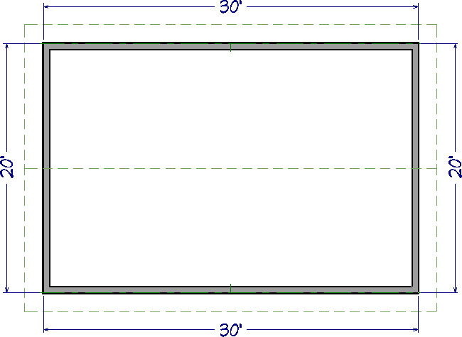
- In this example, a 20' x 30' rectangular structure with a 6:12 gable roof is used.
- For instruction on how to create a gable roof, please visit the Related Articles section below.
- Using the Select Objects
 tool, click on the ridge edge of the roof plane that will be below and in front of the clerestory wall to select it.
- Click on the temporary dimension that tells you how far the ridge is from the baseline.
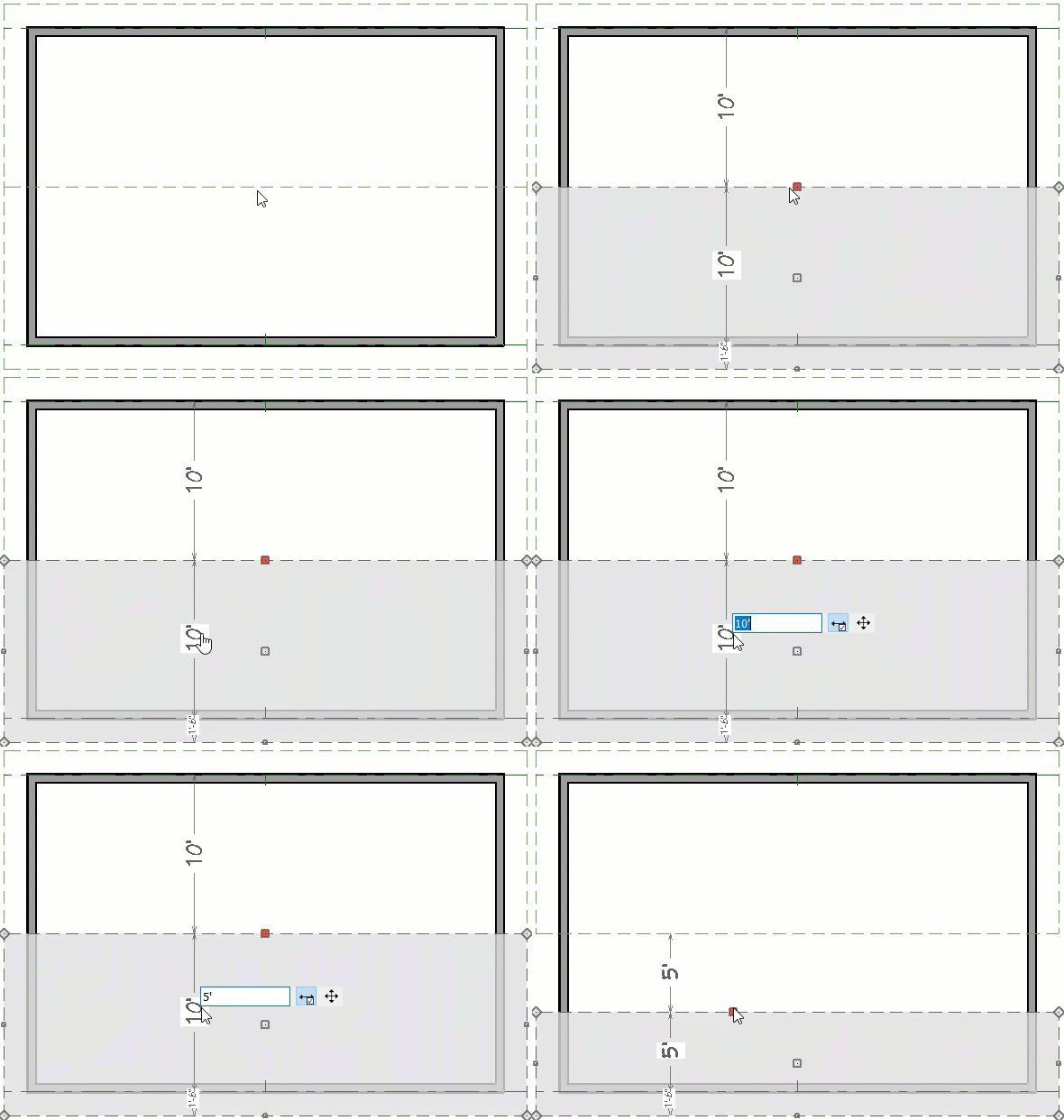
- In the inline text field, type how far in from the baseline the roof plane should extend to meet the interior surface of the clerestory wall and press Enter on your keyboard.
- If you have Auto Rebuild Roofs enabled, click Yes on the Question dialog that appears to turn off Auto Rebuild Roofs so that manual changes can be made to the selected roof plane.
- In this example, a value of 5' (feet) is used.
- If you do not see a temporary dimension when selecting a roof plane, select View> Temporary Dimensions
 to turn on this feature.
- Go Up One Floor
 and select Tools> Floor/Reference Display> Reference Display
  to turn on the Reference Display.
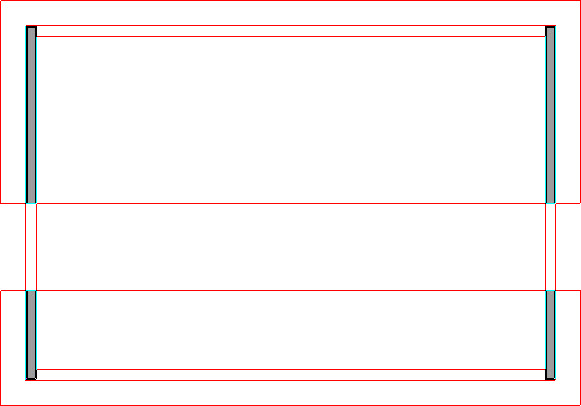
- When the Reference Display is enabled, objects on another floor of the plan, such as roof planes and walls, display for reference. By default, the objects in the Reference Display are red.
- Select Build> Wall> Straight Exterior Wall
 , then click and drag, from right to left, to draw a wall. This wall will become the clerestory.
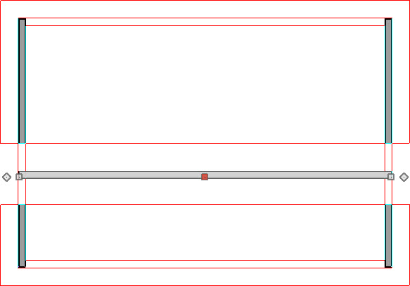
- Do not worry about positioning it precisely as you draw as the wall can be moved to the correct location accurately in a moment.
- If you draw the wall on the Attic floor, a warning message may display as you draw. Click OK to continue.
- Click on the newly drawn wall to select it, then click the Open Object
 edit button.
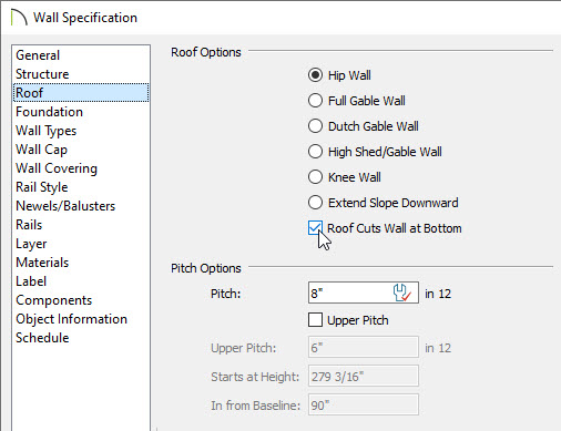
- On the Roof panel of the Wall Specification dialog that opens, check Roof Cuts Wall at Bottom, then click OK.
- With the wall still selected, use its Move
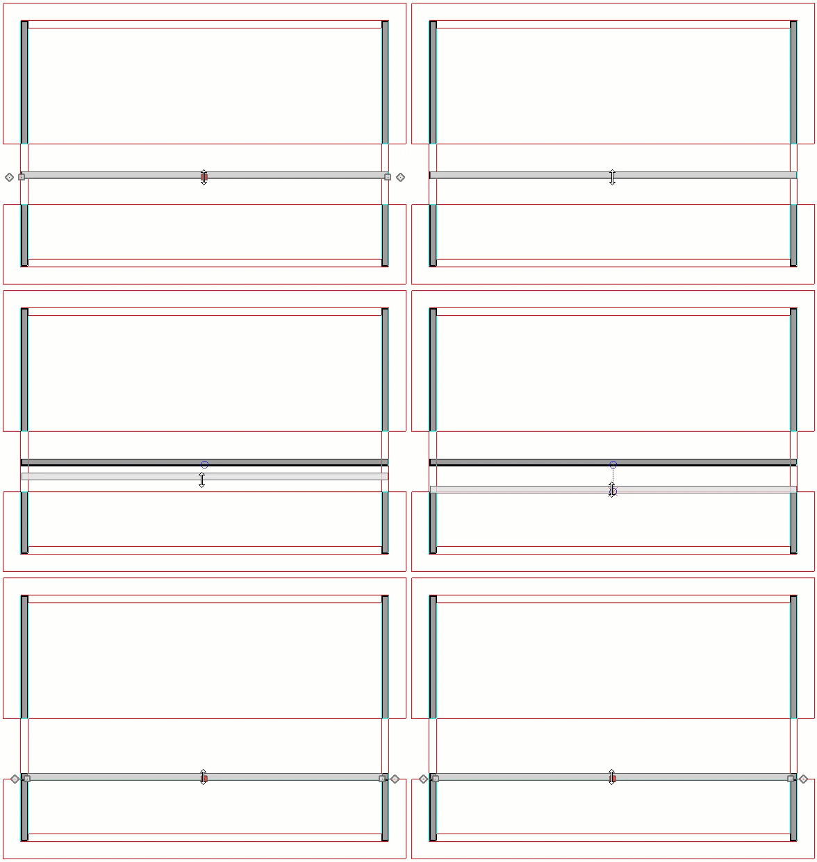
 edit handle to reposition the wall so that its exterior surface snaps to the ridge edge of the roof plane edited in step 3.
- You may want to Zoom
 in to make sure the exterior surface of the wall is snapping to the roof plane edge.
- When the wall snaps to the roof plane edge in the Reference Display, an intersection snap indicator will display on one side of the roof plane edge where it intersects with an attic gable wall.
- To snap the wall to the roof plane, make sure that Object Snaps
 , and particularly, Intersection Snaps
  are enabled.
- When the clerestory wall is in the correct position, go Down One Floor
 .
.
- Using the Select Objects
 tool, click on the roof plane in front of the clerestory wall to select it and extend the top edge of the roof plane through the clerestory wall so that it snaps to the interior surface of the wall.
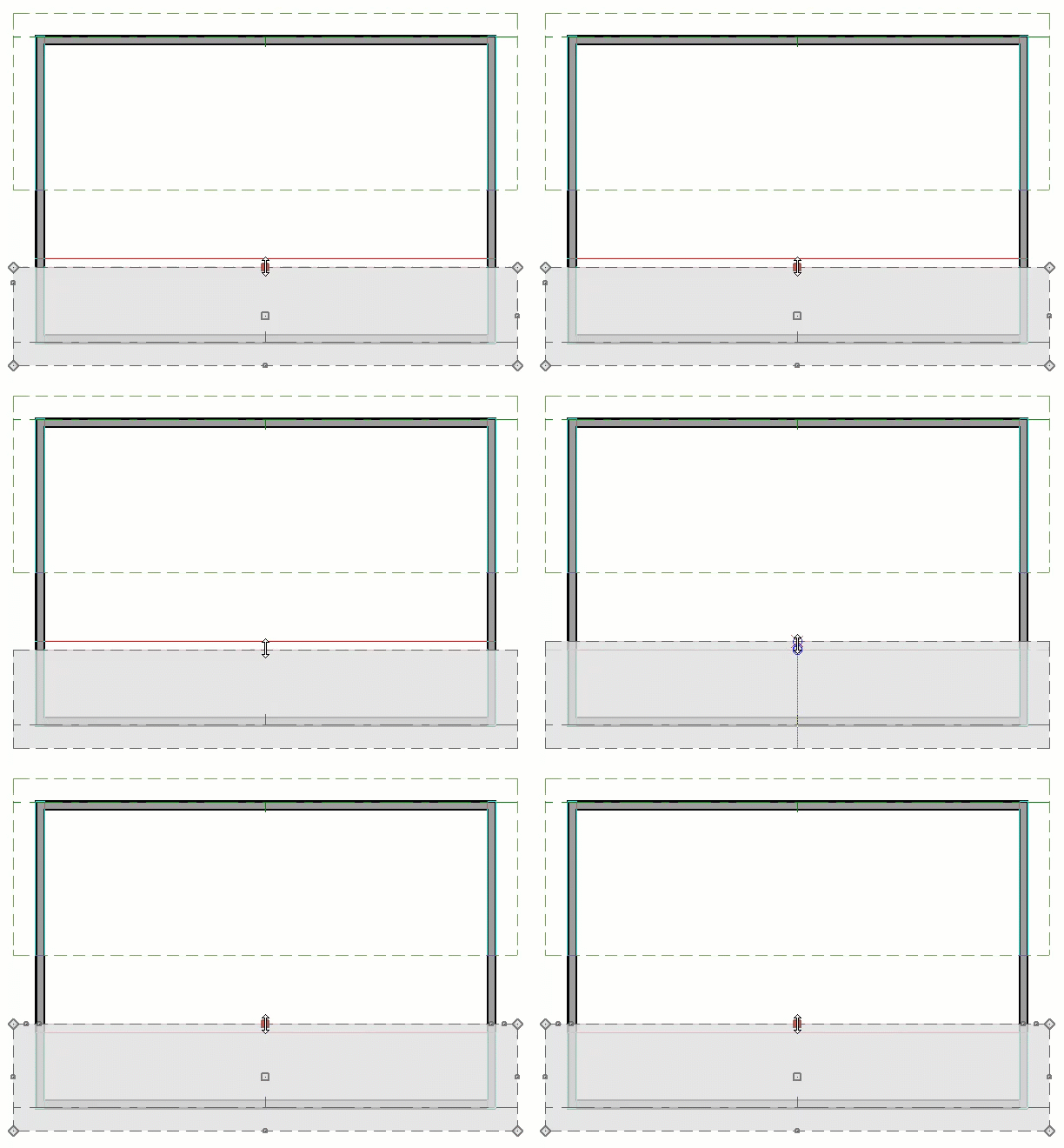
Zoom in to make sure that the roof plane snaps to the interior surface rather than the interior Main Layer surface. If you do not, the clerestory wall may not look correct in interior 3D views.
- Now, use the Select Objects
 tool to select the ridge edge of the other roof plane. This edge can now be extended forward to cover the clerestory.
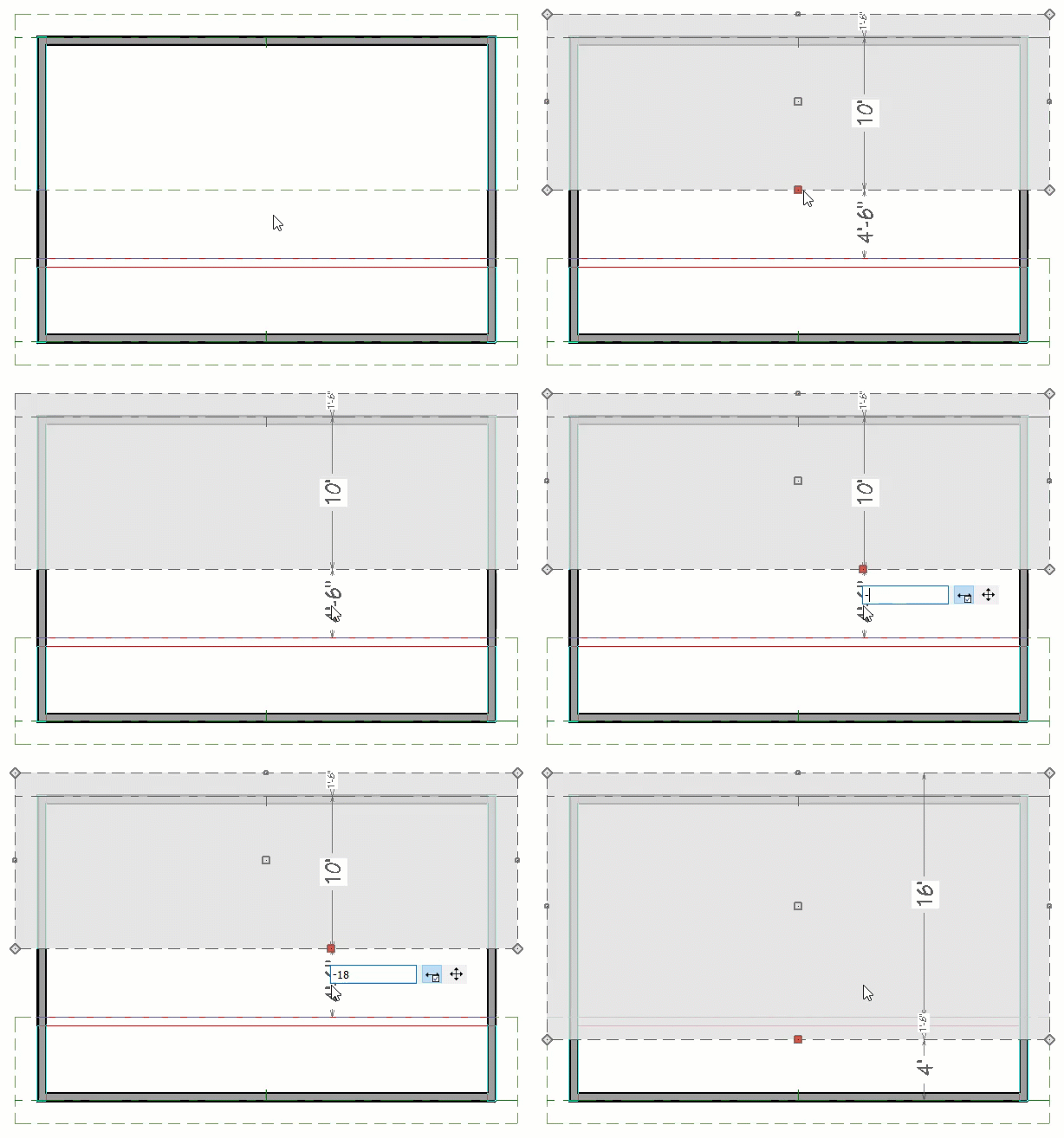
- Click on the temporary dimension indicating the selected edge's distance from the ridge edge of the other roof.
- In the inline text field, type the distance inside the wall's dimension layer that the eave edge should be moved to. To move the selected edge from the outside of the wall to the inside, use a negative number.
- In this example, the roof plane's ridge edge is positioned 18" in from the wall so a value of -18" (inches) is used.
- Finally, click in an empty space within the room under the clerestory to select it and click the Open Object
 edit button.
- On the Structure panel of the Room Specification dialog that opens, remove the check beside Flat Ceiling Over This Room, then click OK.
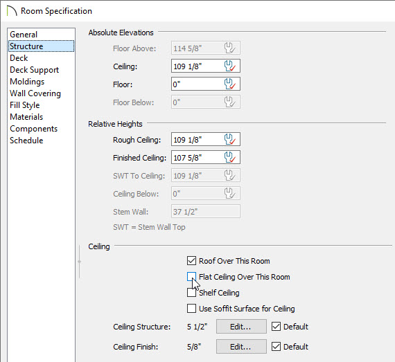
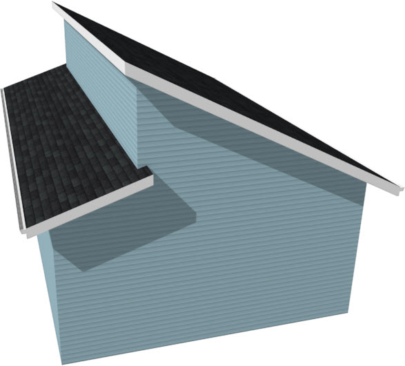
- Finally, take a Camera
 view to see the results.


 , then click and drag, from right to left, to draw a wall. This wall will become the clerestory.
 edit button.

 in to make sure the exterior surface of the wall is snapping to the roof plane edge.

 edit button.
