The information in this article applies to:

QUESTION
What is the best way to approach framing in Chief Architect?

ANSWER
In this tutorial, we will describe recommended framing practices in Chief Architect. Specifically, we will discuss:
Before you begin drawing your plan, it's recommended that you set up your framing defaults to reflect the way you want the structure to be built. Changing these defaults after the structure is complete may cause problems, requiring you to re-do work and lower your productivity.
To setup framing defaults
- Select Edit> Default Settings
 , highlight the Framing category, then click Edit.
- In the Framing Defaults dialog, visit each panel and specify the spacing, framing member size, framing member type, and other information.
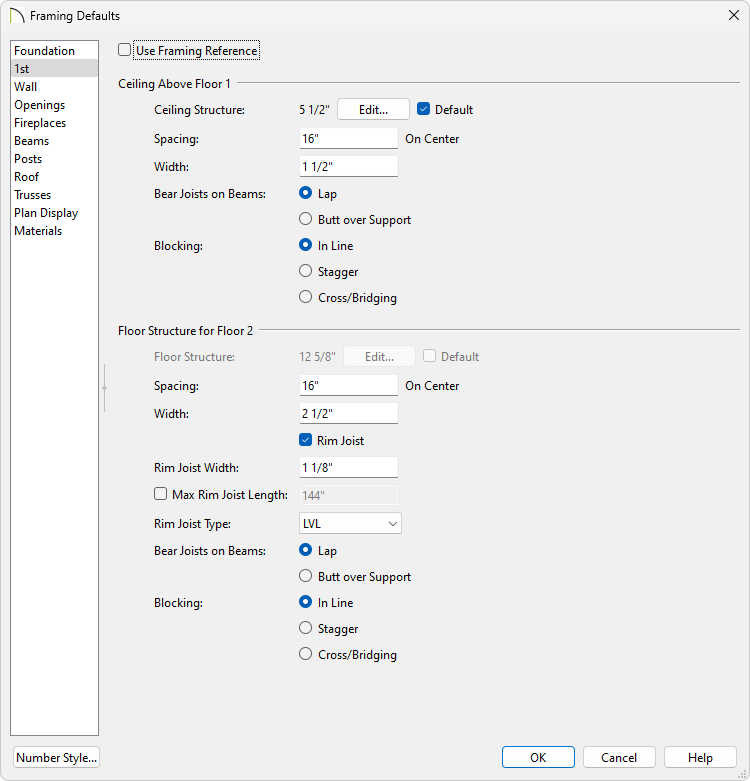
- When you have setup your framing defaults to your satisfaction, click OK.
- Framing layers associated with Wall Types can also be modified to your liking. Navigate to Build> Wall> Define Wall Types
 , and in the Wall Type Definitions dialog that opens:
![]()
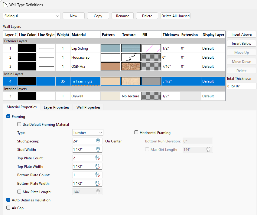
- Choose the Wall Type you'd like to modify using the drop-down menu located in the top left corner.
- Wall layers that are to be framed will typically be listed under the Main Layers category. Select the desired wall layer to make modifications, or select the Insert Above or Insert Below buttons to add a new wall layer above or below the selected layer.
- Specify your desired framing Material as well as an appropriate Thickness value for your framing layers.
- Check Framing to produce framing for the selected layer when wall framing is generated. Select the appropriate framing Type from the drop-down menu, the Spacing, as well as the Width.
In X12 and prior versions, these properties are part of the framing material that is chosen for the wall layer.
- Set your Top and Bottom Plate Count and Width, as well as the Max Plate Length.
These options are not available in X13 and prior versions.
- Check Horizontal Framing to produce framing that runs horizontally instead of vertically, sometimes referred to as girts. When Horizontal Framing is checked, specify the Bottom Run Elevation, which is measured from the center of the lowest horizontal framing member relative to zero, the default top height of the subflooring on Floor 1. Also, specify the Max Girt Length, which is available in X14 and newer versions.
The ability to create Horizontal Framing did not exist in X12 and prior versions.
- Once the framing wall layers are setup to your liking for each of your Wall Types, click OK.
When you are confident that your plan is in its final state, it's a good time to generate framing. You can build framing at any time, however, if changes are made to the plan, manual framing will not update to reflect the changes.
To generate automatic framing
- Select Build> Framing> Build Framing
 from the menu.
In X14 and newer versions, select Build> Framing> Build All Framing  to build roof, wall, platform, and deck framing with a single click.
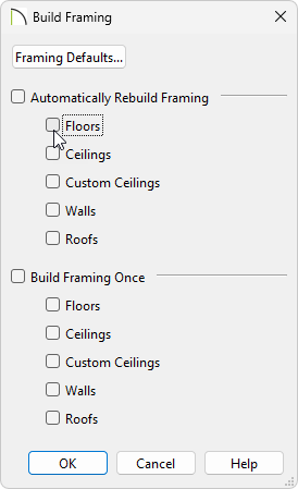
- In the Build Framing dialog, click the Framing Defaults button to open your Framing Defaults and visit each panel to verify that the default information is correct. Once you have verified that the information is correct, click OK.
In X15 and prior versions, only a single Build Framing dialog existed in which framing settings along with Build Framing boxes existed. Visit each panel of this dialog and verify that the information is correct.
Some important framing information to be aware:
- Floor framing for a particular floor in your plan is accessed on the floor below. Floor 1 floor framing, for example, is built on Floor 0 (foundation level), with their settings located on the Foundation panel.
- In order to create the floor framing for Floor 1, a Floor 0 must be present. If a Floor 0 has not been built, the Build Floor Framing checkbox on the Foundation panel will not be available.
- Ceiling framing for a particular floor in your plan is accessed on that floor.
- Starting in X14, the ability to create Roof Overframing is available under the Roof panel.
- In the Build Framing dialog, check the appropriate Build box for each type of framing that you would like to generate, then click OK.
It's common to use a combination of both automatic and manual framing in a single Chief Architect plan.
To build or edit framing manually
With the exception of posts, framing objects are drawn by clicking and dragging in a straight line, similar to other line-based objects. The manual framing tools, which can be accessed by navigating to Build> Framing from the menu, are organized into categories: general framing, roof framing, and floor/ceiling framing. The category that a drawing tool belongs to determines where it can be used:
- Roof framing objects can only be drawn within the area of one or more roof planes.
- Floor and ceiling framing objects can only be drawn within one or more floor or ceiling platforms.
-
General Framing
 objects and Posts
  can be drawn anywhere in a model.
-
General Framing objects can also be drawn in CAD Details.
-
Wall Bridging
 can only be drawn in a Wall Detail.
Manually drawn floor, ceiling, and roof framing is unaffected when automatic framing is rebuilt and remains along with the newly produced automatic framing. In contrast, manually drawn wall framing is deleted when automatic framing is rebuilt. You can, however, prevent this from happening by checking the Retain Wall Framing option located in the Wall Specification dialog.
- Once framing is automatically generated or manually created, it can be edited further.
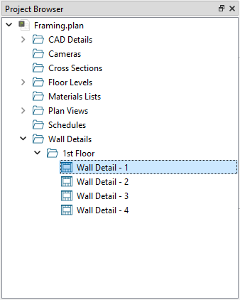
- Use Wall Detail views to edit wall framing components. Wall Details can be accessed from the Project Browser or by right-clicking on a wall and selecting the Open Wall Detail
 edit button.
If you do not see the Project Browser, select View> Project Browser  to turn on its display.
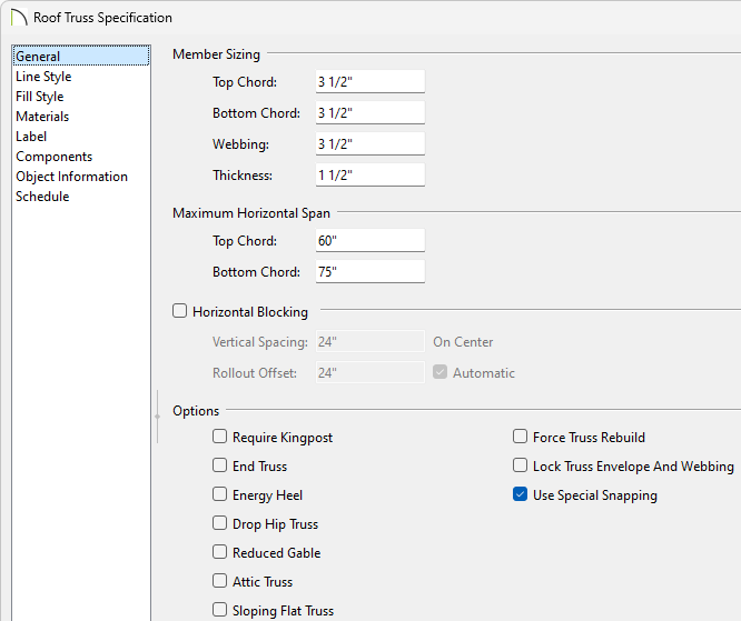
- Floor and roof trusses can be edited by selecting and opening their specification dialog. The chord and webbing thicknesses can be set, as well as horizontal span and some additional options like Kingpost and Energy Heel.
Additional information on each of the options in this dialog can be found by clicking the Help button at the bottom.
![]()
- Trusses can also be modified in the Truss Detail. A Truss Detail is a special CAD Detail window in which a diagram of each truss configuration present in the plan is drawn.
The trusses in a Truss Detail are linked to the actual trusses in the plan. If you modify a truss in a Truss Detail, it will be modified in the model as well. To modify the information in a Truss Detail without affecting the model, use CAD> CAD Detail From View  to create a line-drawn copy first.
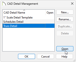
To open a plan’s Truss Detail, select CAD> CAD Detail Management  from the menu, select the Truss Detail, then click Open.
To change framing defaults in an existing plan
- Before making changes that will affect floor, ceiling and/or roof plane heights, it is recommended that you first delete your framing - including wall framing.
- Click On Edit> Delete Objects
 to open the Delete Objects dialog box.
- Click the radio button beside All Floors.
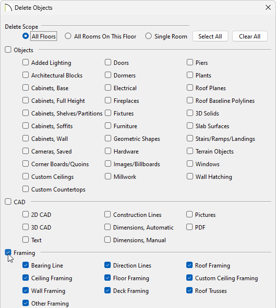
- Check the boxes in the Framing category that you want to remove, or select the Framing heading to check all of the boxes in this category.
- Click Delete to close the dialog and delete the specified framing objects in your plan.
- If you are raising or lowering your floor and/or ceiling heights and you do not have Auto Rebuild Roofs turned on, you may need to raise or lower your roof manually.
- To raise the roof planes enough to accommodate your changes, hold down the Shift key, select the roof planes you'd like to modify, then click the Transform/Replicate Object
 edit button.
To learn more about group selecting objects, such as roof planes, please see the appropriate resource in the Related Articles section below.
- In the Transform/Replicate Object dialog that displays, check the box beside Move, select the Relative To Itself radio button, then specify the desired distance to raise or lower the roof planes along the Z Delta.
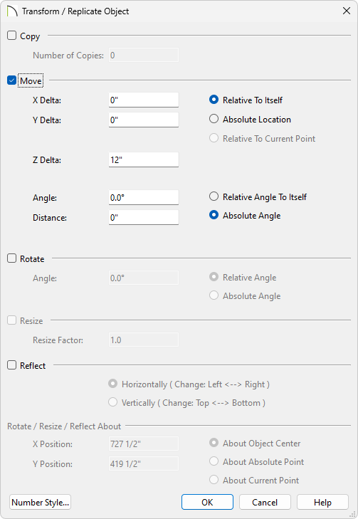
A positive number here will raise the roof planes while a negative number will lower the roof planes.
- Make the needed changes to your plan's structure and framing defaults.
- Begin on the lowest floor and work upwards towards the attic.
- Remember that changes made to the Framing and Floor Defaults will not affect any rooms that are not using the default values. For example, rooms with sunken floors should be examined individually and their heights adjusted as needed.