The information in this article applies to:

QUESTION
The project that I'm working on has custom doors and windows of varying sizes, including a number of mulled units. How do I control the framing for these wall openings?
ANSWER
There are a variety of ways to control how doors and windows are framed in Chief Architect. You can model the wall framing required for nearly any wall opening:
- Using door and window framing defaults;
- Using specifications for individual doors and windows;
- By manually editing door and window framing.
To set door and window framing defaults
Door and window framing defaults are set in two places: on the Framing panel of the Door and Window Defaults dialogs and on the Openings panel of the Framing Defaults dialog.
As with other default settings, it is wise to set your door and window framing defaults to the values that will be used most often as early as possible in the design process.
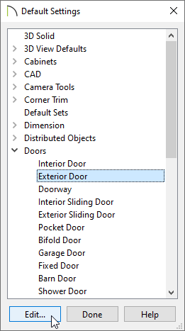
- Navigate to Edit> Default Settings
 .
.
- In the Default Settings dialog that displays, expand the Doors category, select Exterior Door, then click Edit.
- On the Rough Opening* panel of the Exterior Door Defaults dialog:
*Applies to X14 and newer program versions. Rough opening properties for X13 and prior versions can be specified on the Framing panel.
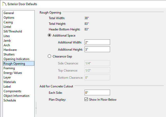
- Select Additional Space or Clearance Gap, then specify your desired values in the available fields.
When Additional Space is selected, the rough opening is equal to the specified size of the door or window plus any specified additional space. When Clearance Gap is selected, the rough opening for doors is equal to the specified size of the door plus the thickness of its jamb plus any values specified. For windows, the rough opening is equal to the specified size plus any values specified.
In X14 and prior versions, these options weren't available; instead, specify the amount to add to Each Side, the Top and the Bottom for the door’s framed rough opening. The rough opening should be large enough to accommodate the door frame and space for shims. Window frames do not need to be included in the rough opening.
- Under Add for Concrete Cutout, specify the amount to add to Each Side of the door opening when the upper part of the door is in a framed wall and the lower part is located in a concrete or masonry wall, stem wall, or garage curb.
- Uncheck Show In Floor Below to suppress the display of the concrete cutout in plan views.
In X15 and prior versions, this was called Show in Plan.
- On the Framing panel of the Exterior Door Defaults dialog:
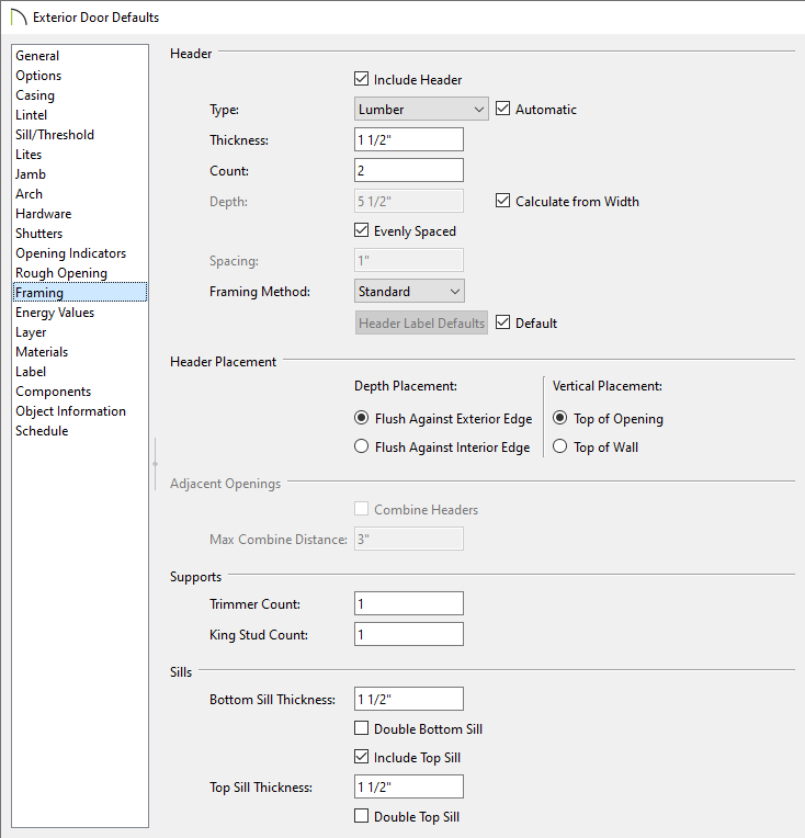
- Specify the Header Type, Thickness, Count, Depth, Spacing, and Framing Method*.
Keep Calculate from Width checked if you want the Header depth determined by the width of the door. The Calculate from Width settings are located in the Framing Defaults, which are discussed in Step 6 below.
When Evenly Spaced is checked, the boards that comprise the header are evenly spaced within the wall's framing layer. Uncheck this box to specify the spacing of the header boards.
*Applies to X16 and newer program versions. In X15 and prior versions, a box header can be specified by checking the Box Header box.
- Specify the Depth and Vertical Placement options. If the Vertical Placement is set to Top of Wall, the Combine Headers box can be checked and a Max Combine Distance value can be specified.
- Specify the Trimmer Count and the King Stud Count*.
*Applies to X14 and newer program versions.
- Specify any properties related to Sills.
- Specify any other settings, then click OK to apply your settings.
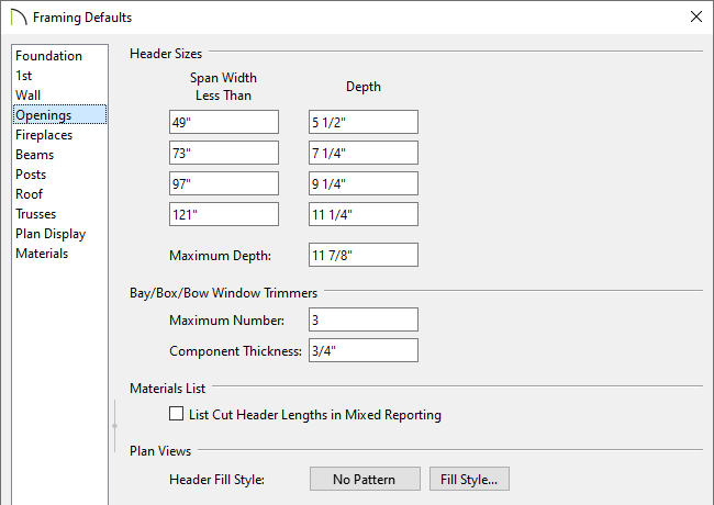
- Remaining in the Default Settings dialog, expand the Framing category, select General Framing, then click Edit.
In X15 and prior versions, select the Framing category, then click Edit instead.
- On the Openings panel of the Framing Defaults dialog that displays, you can specify up to four different sizes of headers for wall openings of different widths.
- When you are finished, click OK, then repeat Steps 1 - 6 for the Window defaults, as well as any other Door Defaults that you would like to change.
To specify the framing for an individual door or window
You can specify unique values for individual doors and windows in their specification dialogs. It's best to do this before wall framing is built; if these values are changed after wall framing is generated, you will need to regenerate wall framing again unless the automatic wall framing capability is enabled.
- Select a door or window and click the Open Object
 edit button.
- In the Door or Window Specification dialog, access the Rough Opening and Framing panels, specify your desired values, then click OK.
- If the selected object is a mulled unit composed of multiple windows and/or doors that have been blocked together, you can specify whether the unit is framed using a single opening or separate openings for each door or window on the Options panel.
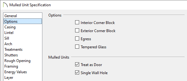
- Check Treat as Door to include the unit in the "Doors" category of the Materials List and in the "Mulled Door Units" Auto Schedule Category. This option is only available when the selected unit contains a door.
- Uncheck Single Wall Hole to produce individually framed wall openings for each unit in a mulled unit. When this box is checked, a single wall opening with a header for the entire unit is produced.
To manually edit door and window framing
Once wall framing has been generated, you can easily edit these framing members, if needed. Plates, sills, headers, trimmers and cripples can be selected in 3D views, cross section/elevation views, and in Wall Details, while studs can be selected and edited in any view. Please see the "Manually Editing Wall Framing" and "General Framing Guidelines" articles in the Related Articles section to learn more.