The information in this article applies to:

QUESTION
I would like to create and display exposed rafter tails in designs. How can I do this?

ANSWER
Rafter tails are rafter ends that overhang the bearing walls and are located under the eaves. They can be the full rafter depth or trimmed to the depth of the soffits and sometimes feature decorative profiles. Rafter tails can also be fully exposed, or partially enclosed by soffits.
This article assumes you have already specified your Roof Framing Defaults, but you have not yet created roof planes. If your plan already has a roof built and Auto Rebuild Roofs is disabled, group select all of the roof planes that will have exposed rafters and complete the steps described below in the Roof Plane Specification instead of the Build Roof dialog.
To create fully exposed rafter tails

- In your desired plan select Build> Roof> Build Roof
 and in the Build Roof dialog that displays:
- On the Roof panel, check the Build Roof Planes box.
Heel height/birdsmouth cut properties can also be adjusted on this panel. For more information, click the Help button located at the bottom of the dialog to open your program's documentation.
- On the Structure panel:
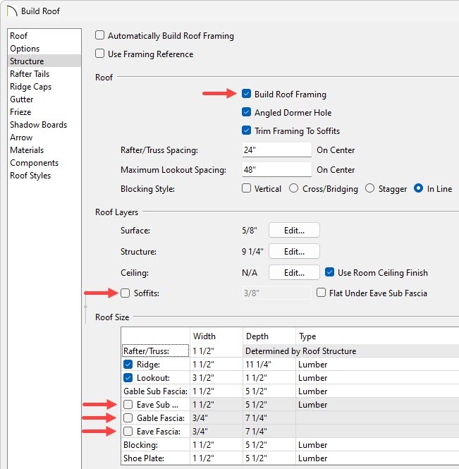
- Check Build Roof Framing.
- Remove the check from Soffits.
- Remove the check from Eave Sub Fascia.
- Remove the check from Gable Fascia or Eave Fascia. Unchecking one will also uncheck the other.

- If a decorative rafter end is going to be used, select the Rafter Tails panel and click Add New to browse the library for a suitable rafter tail profile.

- Click OK to close the dialog and generate the roof.
- Select 3D> Create Perspective View> Perspective Full Overview
 to create a 3D view of the structure.
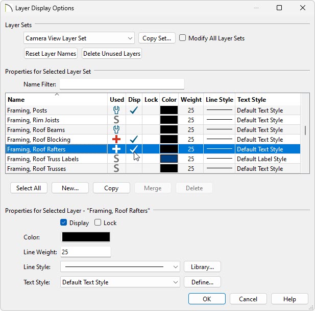
- Framing layers are not displayed in this type of camera view by default. To turn on roof rafters, select Tools> Layer Settings> Display Options
 and in the Layer Display Options dialog that opens:

- Verify that the correct Layer Set is selected.
In this example, the Camera View Layer Set is selected, which is the default for the Perspective Full Overview tool.
- Locate the "Framing, Roof Rafters" layer and place a check in the Disp column.
- Click OK to confirm the change and close the dialog.
To create partially exposed rafter tails

- In your desired plan select Build> Roof> Build Roof
 and in the Build Roof dialog that displays:
- On the Roof panel, check the Build Roof Planes box.
Heel height/birdsmouth cut properties can also be adjusted on this panel. For more information, click the Help button located at the bottom of the dialog to open your program's documentation.
- On the Structure panel:
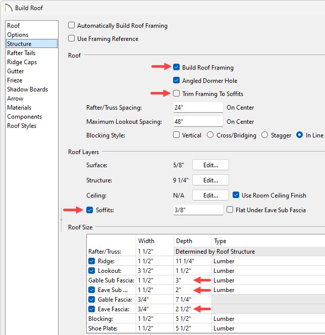
- Check Build Roof Framing.
- Remove the check from Trim Framing to Soffits.
- Check Soffits.
- Check and specify the Fascia and Sub Fascia Depths, if desired.
In this example, the Gable Sub Fascia Depth is set to 3", the Eave Sub Fascia Depth is set to 2", and the Eave Fascia Depth is set to 2 1/2", though these will likely vary for your roof, depending on what you want to show.

The Soffit height, along with its elevation, is determined by the depth of the Gable Sub Fascia.
-
- If a decorative rafter end is going to be used, select the Rafter Tails panel and click Add New to browse the library for a suitable rafter tail profile.

- Click OK to confirm the changes and close the dialog.
- Select 3D> Create Perspective View> Perspective Full Overview
 to create a 3D view of the structure.
- Framing layers are not displayed in this type of camera view by default. To turn on roof rafters, select Tools> Layer Settings> Display Options
 and in the Layer Display Options dialog that opens:

- Verify that the correct Layer Set is selected.
In this example, the Camera View Layer Set is selected, which is the default for the Perspective Full Overview tool.
- Locate the "Framing, Roof Rafters" layer and place a check in the Disp column.
- Click OK to confirm the change and close the dialog.


