The information in this article applies to:

QUESTION
I created a CAD block that I would like to add to the library for future use, and am interested in adding a point to it to help control how it gets placed. Do you have any suggestions?
ANSWER
By default, a CAD block has one insertion point located at its center. When placing the CAD block in a drawing or moving it to a new location, you can snap its insertion point to some other snap point for accuracy.
In some cases, it may be helpful to position a CAD block using an insertion point other than its center. In these instances, you can use the Add Insertion Point tool in a CAD Block window in X15 and newer versions, or the Select Insertion Point edit tool.
To use the Add Insertion Point tool
Applies to Chief Architect X15 and newer versions.
-
Open
 the plan in which you have created a CAD block that requires a custom insertion point.
In this example, we will add an insertion point to a CAD block representing a J bolt.

- Select Edit> Snap Settings
 from the menu, verify that Object Snaps
  are enabled, then make sure the various object snap settings have checks next to them. These include Endpoint
  , Midpoint
  , Center
  , etc.
- Using the Select Objects
 tool, click on the CAD block to select it, then click the Edit CAD Block
  edit tool.
- In the CAD Block window that appears, navigate to CAD> CAD Blocks> Add Insertion Point
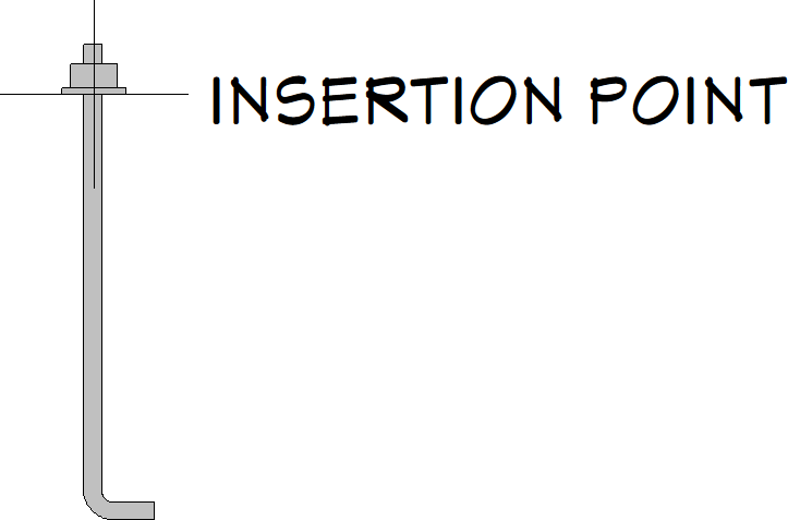
 , then click where you would like the insertion point to be. A cross will appear at the point that you clicked with text mentioning that it's an insertion point.

A CAD block’s insertion point can also be specified relative to the blocks’ center point in the CAD Block Specification dialog. Please see your program's Help documentation to learn more.
- With the insertion point in your desired location, navigate to Tools> Active View> Save Active View
 . A Question window may appear asking if you want to replace any current instances with the modified block. Choose your desired option to continue.
- The modified CAD block can now be added to your User Catalog using the Add to Library
 edit tool.
To use the Select Insertion Point edit tool
-
Open
 the plan in which you have created a CAD block that requires a custom insertion point.
In this example, we will add an insertion point to a CAD block representing a J bolt.

- Select Edit> Snap Settings
 from the menu, verify that Object Snaps
  are enabled, then make sure the various object snap settings have checks next to them. These include Endpoint
  , Midpoint
  , Center
  , etc.
- Using the Select Objects
 tool, click on the CAD block to select it, then click the Explode CAD Block
  edit tool.
The Select Insertion Point edit tool can also be used without having to explode the the CAD block; however, the available snap points will be limited to the perimeter of the CAD block's boundary box, as well as the center of the block.
- Next, navigate to CAD> Points> Place Point
 , then click to place a temporary point where you would like the insertion point to be.
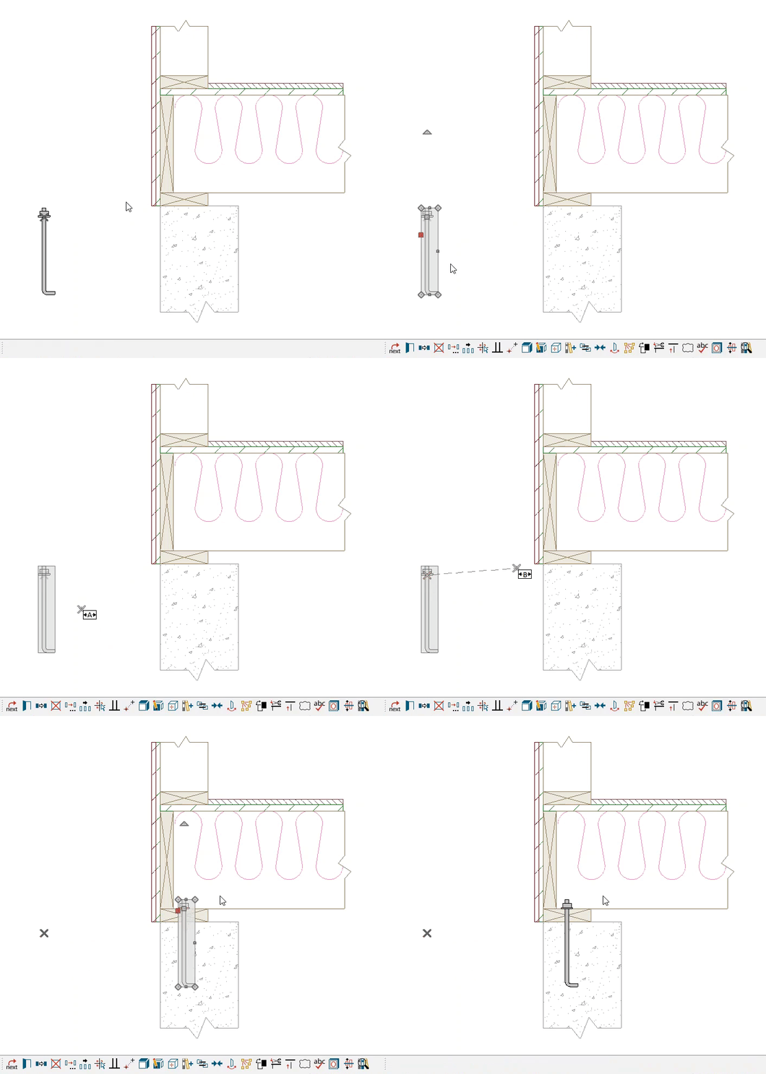
In this example, the temporary point is placed along bottom edge of the washer, specifically at the center point. This is displayed as a gray "x", as shown in the image below.

- Click on the Select Objects
 tool, create a selection marquee around the CAD components, then click the Made CAD Block
  edit tool to block them together again.

- With the CAD block selected, click on the Select Insertion Point
 edit tool, then click on the temporary point to set the insertion point. A Move
  edit handle will appear at this location, as shown in the image below.

A CAD block’s insertion point can also be specified relative to the blocks’ center point in the CAD Block Specification dialog. Please see your program's Help documentation to learn more.
- You can now accurately position the CAD block with the custom insertion point using the Point to Point Move
 edit tool, and/or add it to your User Catalog using the Add to Library
  edit tool.

For more information on the Point to Point Move and Add to Library edit tools, please see the Related Articles section below.
- Notice that the temporary point placed in Step 4 will not move with the CAD block, nor will it be part of the CAD block if it's added to the library. This does not affect the insertion point that was set. You can delete the temporary point by navigating to CAD> Points> Delete Temporary Points
 from the menu.


 from the menu, verify that Object Snaps

 from the menu, verify that Object Snaps


