The information in this article applies to:

QUESTION
Can you offer some suggestions for creating cabinet details?

ANSWER
Cabinet elevations can easily be created using the Wall Elevation and Dimension tools. Additionally, Chief Architect Premier can convert an elevation view to a2D CAD drawing using the CAD Detail from View tool.
In this article we will cover:
To create a cabinet elevation
- In the plan you'd like to detail, select 3D> Create Orthographic View> Wall Elevation
 from the menu, then click and drag to draw a camera arrow directly towards the front of the cabinets you wish to detail.
The Cross Section/Elevation and Backclipped Cross Section tools can also be used to create a cabinet elevation; however, these tools may display additional rooms and/or floors by default.
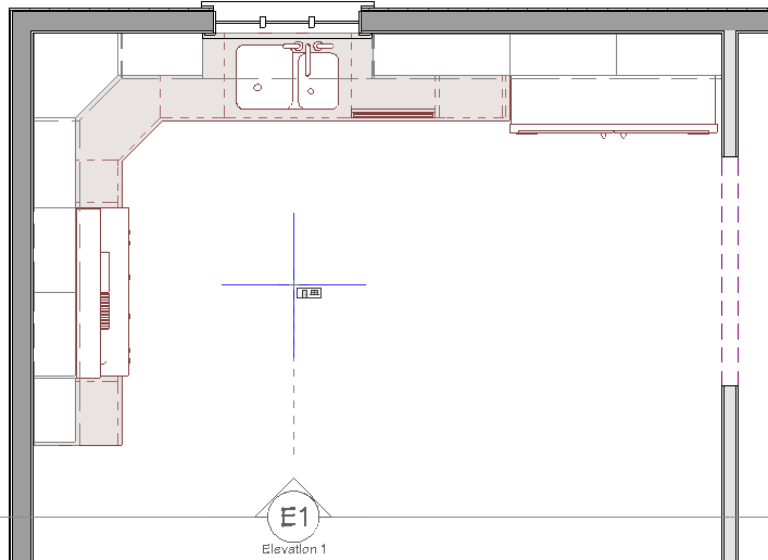
- If needed, use the Zoom
 tools to zoom in on the cabinets you would like to detail.
If you find it helpful, you can also select View> Color to toggle off the color while in the elevation view.
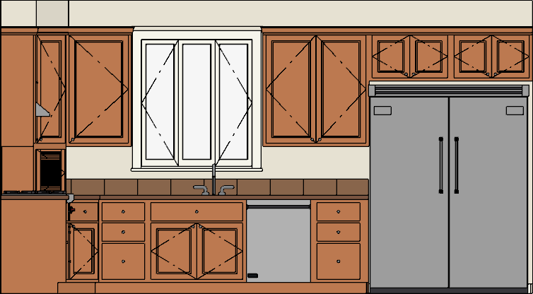
- If you see objects such as decorative furnishings, electrical fixtures, or labels that you do not want in the view, you can turn off their display in the Layer Display Options dialog or within the Active Layer Display Options
 side window.
- To open the Layer Display Options dialog, select Tools> Layer Settings> Display Options
 from the menu.
- The Active Layer Display Options
 side window is displayed on the right side of the screen by default. You can toggle the display of this window on and off by navigating to View> Active Layer Display Options
  .
.
- Select Tools> Active View> Save Active View
 from the menu, then select Tools> Active View> Edit Active View
  .
.
- On the Camera panel of the Wall Elevation or Cross Section/Elevation Specification dialog that displays:.
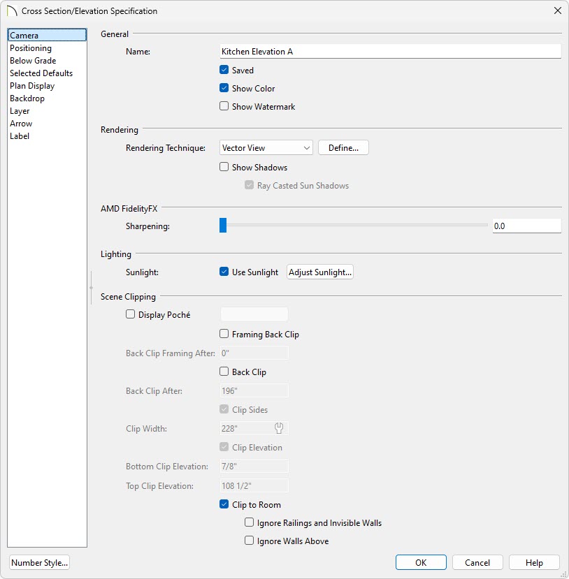
- Type a short name for your saved cabinet elevation in the Name field, such as Kitchen Elevation A.
- Choose your desired rendering options.
- Uncheck Clip to Room if you would like to manually control where the view is clipped along the bottom, top, and both sides of the elevation.
For more information on manually controlling the elevation's clipping, please see the Related Articles.
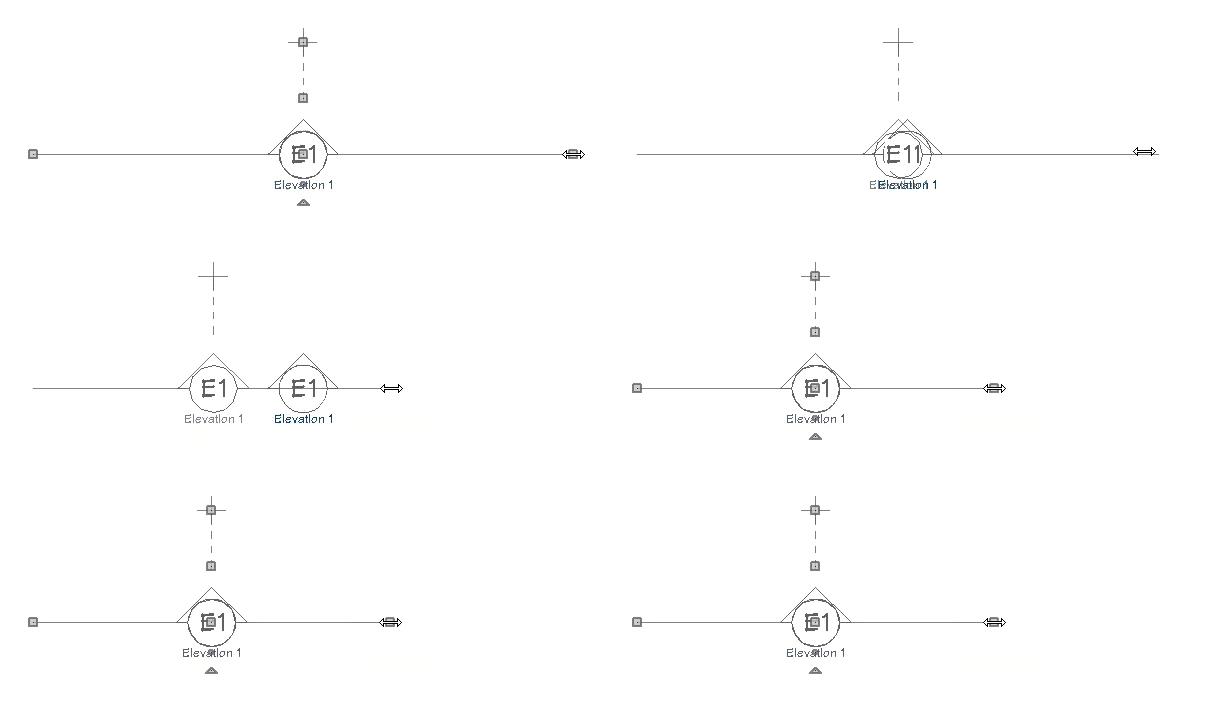
Once the Clip to Room setting is unchecked, you may find that it easier to adjust the side clipping of the elevation using the edit handles that display in a floor plan view.
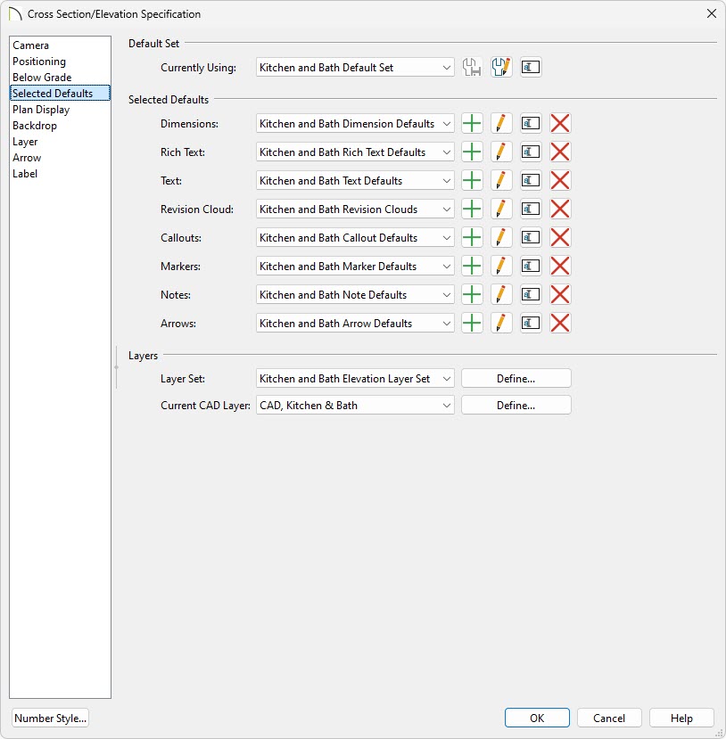
- Click on the Selected Defaults panel, make sure the settings here are setup to your liking, then click OK.
In this example, the Kitchen and Bath Default Set is specified, the Kitchen and Bath Elevation Layer Set is selected, and CAD, Kitchen & Bath is the current CAD layer for this view. Take note of the Dimension Default that is also set here, as this will be discussed in the next section.
To configure dimension defaults
- Select Edit> Default Settings
 from the menu, and in the Default Settings dialog:
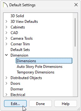
- Click the arrow next to Dimension.
- Select Dimensions and click the Edit button.
- In the Saved Dimension Defaults dialog that opens next, select the Dimension Default that was specified for the elevation view in the section above, then click Edit.
If you recall, we are using the Kitchen and Bath Default Set, which is connected to the Kitchen and Bath Dimension Defaults.
- In the Dimension Defaults dialog:
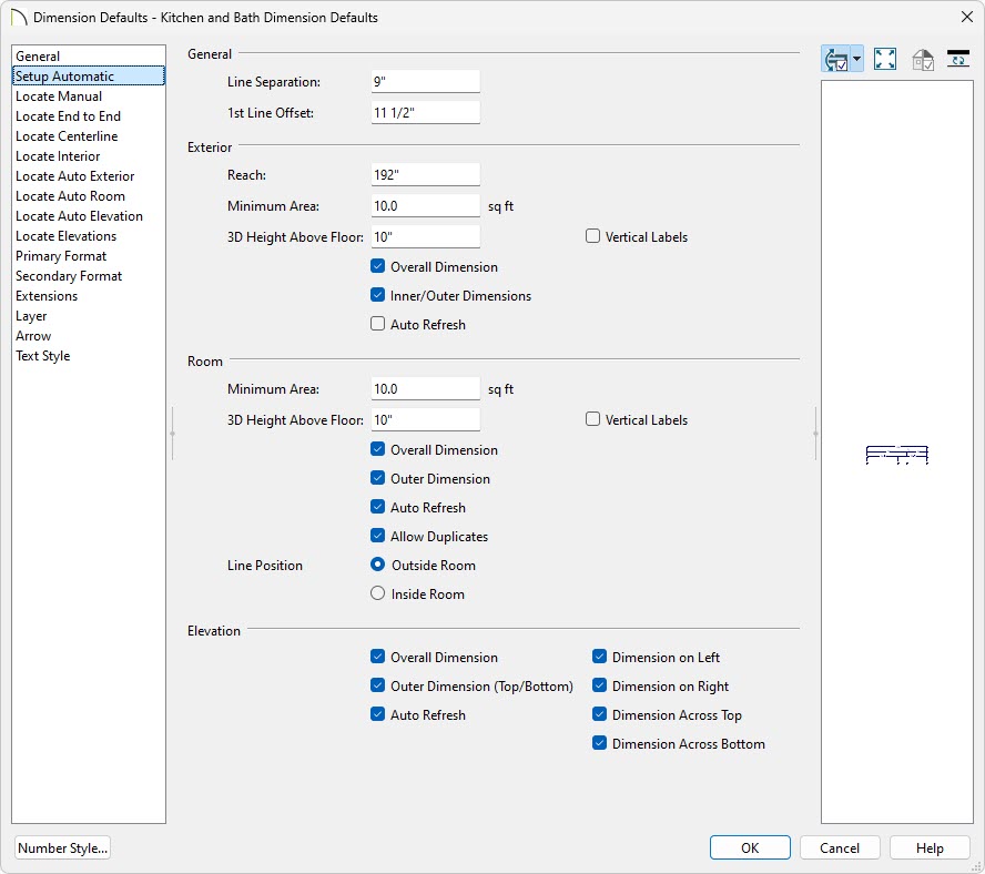
- Select the Setup Automatic panel and check the desired boxes in the Elevation section if you will be creating automatic dimensions.
- Access each of the Locate... panels, and choose what you would like each of the dimension tools to locate.
- On the Primary Format panel, select the desired Units, Accuracy, and Dimension Text Position and Orientation.
- Adjust the Extension line, Arrow, Layer, and Text Style properties to your liking.
To learn more about the various settings relating to dimensions, select the Help button located at the bottom of the dialog.
- Click OK to close the dialog and apply your changes.
To add dimensions
- Dimension lines can be added to an elevation view automatically or manually:
- To generate dimensions automatically, navigate to CAD> Automatic Dimensions> Auto Elevation Dimensions
 .
.
- To generate dimensions manually, navigate to CAD> Dimensions
 , select your desired tool, such as the Manual Dimension
  or End to End Dimension
  tool, then click and drag to draw a dimension line through one of the cabinets that you would like to detail.
- Once dimensions are created, they can be edited further to your liking. Using the Select Objects
 tool, click on a dimension line, near the dimension number, to display various edit handles.
In this example, a dimension line that is displayed along the bottom edge of the elevation is selected.
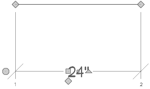
- In the image above, the numbers displayed at the bottom represent each extension line. You can see that the extension line on the left (1) is the very first extension line in this dimension string.
- The diamond-shaped edit handles near the top are Extension Line edit handles. Select and drag these handles to move an extension line to another location or object.
To delete an extension line, drag an Extension Line edit handle away from any dimensionable object, and release the mouse button once the line disappears.
- Use the large square Move edit handle located near the dimension number to move the dimension string in your desired direction.
- The diamond-shaped edit handle just below the Move edit handle is the Add Extension Line edit handle. Drag this handle to an object that you want to locate, then release the mouse button.
- The smaller square edit handle in the middle of the dimension number allows you to relocate the dimension number, while the triangular edit handle will rotate the dimension number.
- Use the circle edit handle to add a segment onto the end of the dimension line, and use the large triangular edit handle (not pictured) to rotate the dimension string.
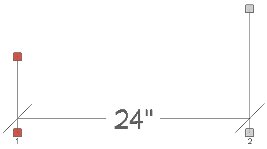
- Extension lines can also be selected separate from the dimension line. When an extension line is selected, the square edit handles that display can be used to resize the line's length.
In the image below, you can see that the left extension line (1) was resized to be shorter than the right extension line (2).
- With either the dimension line or extension line selected, click the Open Object
 edit button to open the Dimension Line Specification dialog.
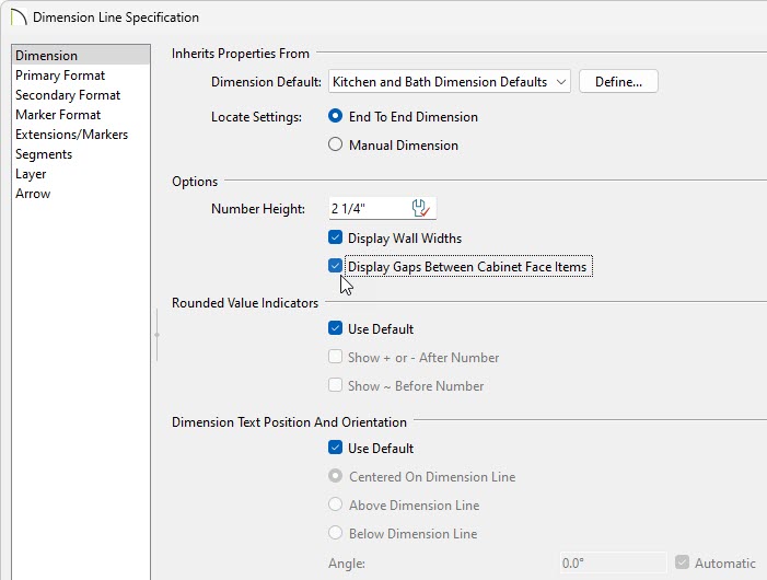
- On the Dimension panel, notice that the dimension line is following the Dimension Default that was set in the first section of this article.
- Check the Display Gaps Between Cabinet Face Items box if you would like the opened dimension line to display dimension numbers for built-in appliances, blank areas, openings, and other gaps between cabinet face items.
- Make any other desired adjustments to the dimension line, then click OK to close the dialog.
- Add any additional information, such as Text
 , Leader Lines
  , and Notes
  to the detail, then select Tools> Active View> Save Active View
  one final time.
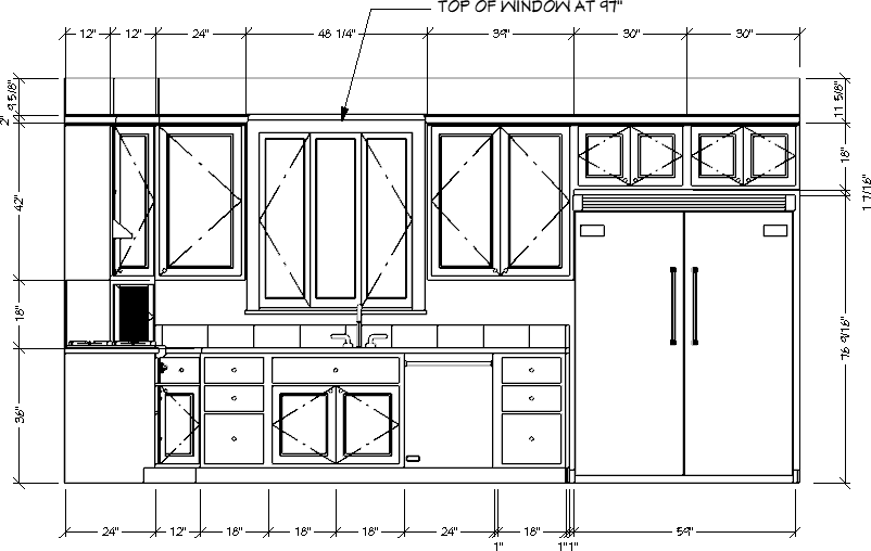
- This view can now be sent to a layout file using the Send to Layout
 tool.
tool.
In Chief Architect Premier, you can also add, change, or delete unwanted lines in the view by converting it into a CAD drawing using the CAD Detail from View tool.
To create a CAD Detail from an elevation view*
*Applies to Chief Architect Premier Only
- With your saved elevation view open, select CAD> CAD Detail from View
 from the menu.
- Select CAD> CAD Detail Management
 from the menu, and in the CAD Detail Management dialog:
- Click on the name of your new CAD Detail. Its name will begin with "Elevation" followed by a number, and it will be indicated as open under the Open column.
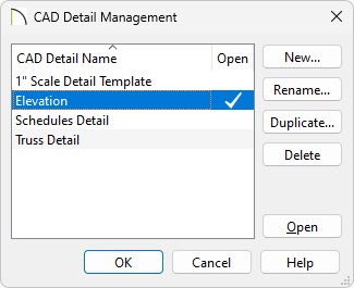
- Click Rename and type a short, descriptive name for your detail, then click OK.
- Click OK to close the dialog and return to your CAD Detail.
To delete or trim unwanted CAD lines
- Using the Select Objects
 tool, select any lines that you want to remove from the detail, then Delete
  them.
them.
- If you'd like to trim CAD lines, you can do so using the Trim Objects
 edit tool.
- To trim all CAD objects around a certain area, select CAD> Boxes> Rectangular Polyline
 from the menu, then click and drag a rectangle around the portion of the drawing that you want to keep for your detail.
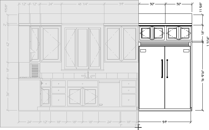
- Don't worry about positioning it accurately as you draw. Once the polyline is created it can be edited with precision.
- In addition to the edit handles, the polyline's edit tools can be used to resize, reshape, and move it into position.
- When the polyline has been edited to your liking, select it, and click the Trim Objects
 edit tool.
- Click and drag to draw a temporary line just outside one edge of the polyline.
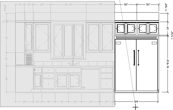
- This temporary line is called a fence and it will select every line intersecting your polyline, and delete the portion of that line that is outside the polyline.
- You may find it helpful to turn off Object Snaps
 while drawing temporary fences. This can be done by navigating to Edit> Snap Settings> Object Snaps
  from the menu.
- Repeat steps 4 and 5 for each edge of the polyline, if needed.
- Using the Select Objects
 tool, click and drag to marquee-select any remaining lines outside of the polyline, then Delete
  them.
them.
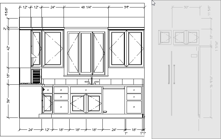
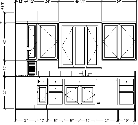
- When you are finished, you may want to select and Delete
 the rectangular polyline as well.

 from the menu, then click and drag to draw a camera arrow directly towards the front of the cabinets you wish to detail.
 tools to zoom in on the cabinets you would like to detail.
 from the menu.


 from the menu, and in the Default Settings dialog:


 edit button to open the Dimension Line Specification dialog.

 from the menu.
 from the menu, and in the CAD Detail Management dialog:
 them.
them. edit tool.
 from the menu, then click and drag a rectangle around the portion of the drawing that you want to keep for your detail.
 edit tool.
 tool, click and drag to marquee-select any remaining lines outside of the polyline, then Delete
  them.
them.
 the rectangular polyline as well.