The information in this article applies to:

QUESTION
How do I create a dropped ceiling?
ANSWER
A dropped ceiling is a secondary ceiling, hung below the main, structural, ceiling. They may also be referred to as a drop ceiling, false ceiling, or suspended ceiling.
To create a dropped ceiling
- In your plan, use the Select Objects
 tool to select the room that you want to assign a dropped ceiling to, then click the Open Object
  edit button.
If you select an object located inside of a room, click the Select Next Object edit button ,or press the Tab key on your keyboard, until the room becomes selected.
- On the Structure panel of the Room Specification dialog that displays, click the Edit button next to Ceiling Finish.

- In the Ceiling Finish Definition dialog that opens next, select the topmost layer, which is Layer # 1, then click the Insert Above button to add a new layer.
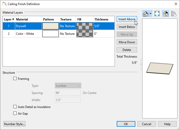
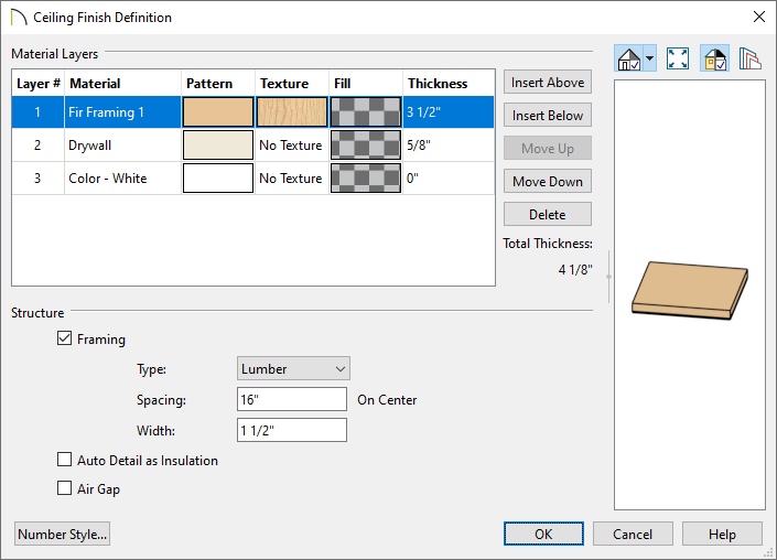
- Specify the desired Thickness of this new layer, which will form the dropped ceiling framing.
In this example, 3 1/2" is used.
- Click within the Material column for the new layer to open the Select Material dialog, and choose your desired framing material.
In this example, the "Fir Framing 1" material is used.
- Under the Structure section, check the Framing box for this layer, then specify the Type, Spacing, and Width, as necessary.
In this example, Lumber is set for the Type, 16" is set for the Spacing, and 1 1/2" is set for the Width.
- Repeat this process if you require additional layers, such as an air gap, above the framing.
In this example, an additional layer was added with a Thickness of 7 7/8" and the material set to "Insulation Air Gap". When adding layers, it's important to check that the properties under the Structure section are set correctly. With this new layer, we made sure that the Framing box was unchecked and checked the Air Gap box instead.
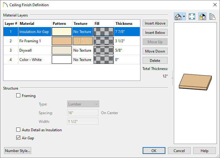
- When you are finished, click OK to return to the Room Specification dialog and notice the ceiling preview on the right. Click OK again to confirm the change and close the dialog.
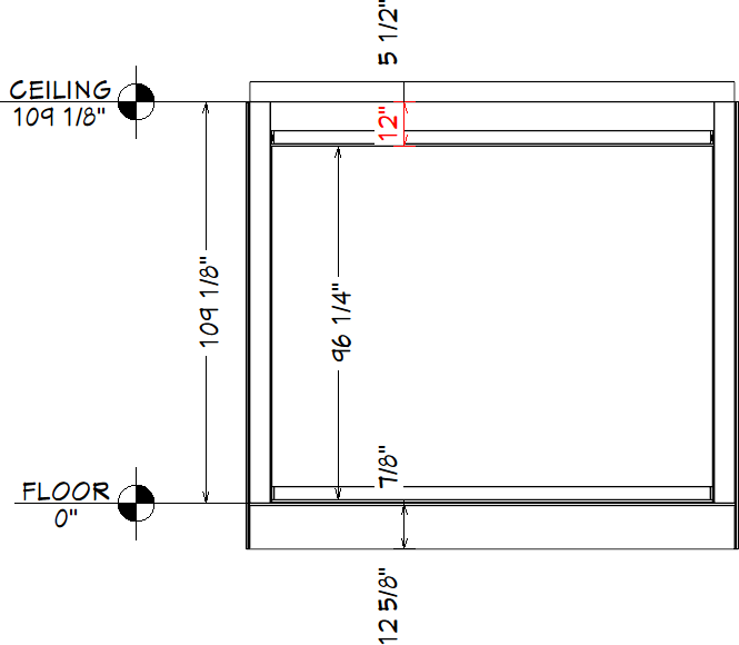
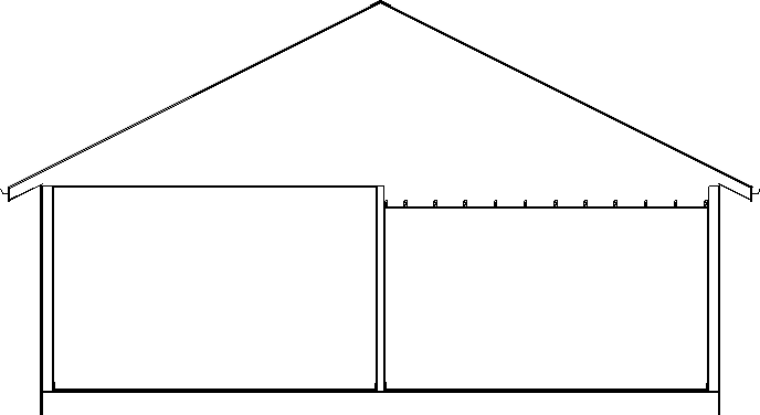
These results can also be seen in a Backclipped Cross Section  view.
view.
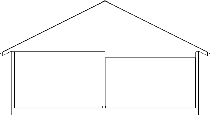
If part or all of the platform above the dropped ceiling is a ceiling platform, a dropped ceiling's framing can be created automatically when ceiling framing is generated.
If, however, the entire platform above the dropped ceiling is a floor platform, the framing may need to be drawn manually.
To manually frame a dropped ceiling
- Select the room with the lowered ceiling and click the Open Object
 edit button.
- On the Structure panel of the Room Specification dialog:
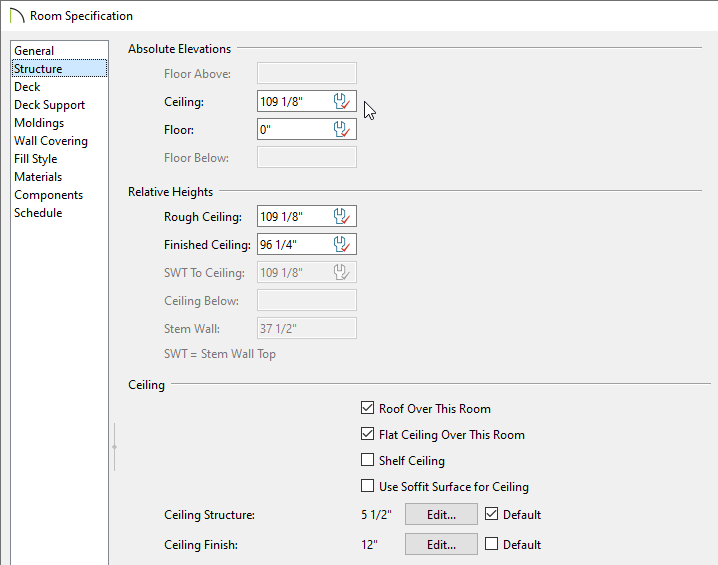
- Take note of the Ceiling height under the Absolute Elevations section.
In this example, this value is 109 1/8".
- Click the Edit button next to Ceiling Finish and take note of the Thickness of the layer(s) located above the framing layer.
In this example, the layer(s) above the framing equal a value of 7 7/8".
- Click Cancel to close both dialog boxes.
- Subtract the thickness of the ceiling finish layers above the framing layer from the ceiling height. The resulting value is the top height of your lowered ceiling framing members.
In this example, we subtracted 7 7/8" from 109 1/8", giving us a value of 101 1/4".
- Select Build> Framing> General Framing
 from the menu, then click and drag to draw a framing member across the room with the lowered ceiling.
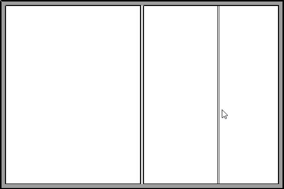
- Click on the joist to select it, then click the Open Object
 edit button.
- On the General panel of the Framing Specification dialog:
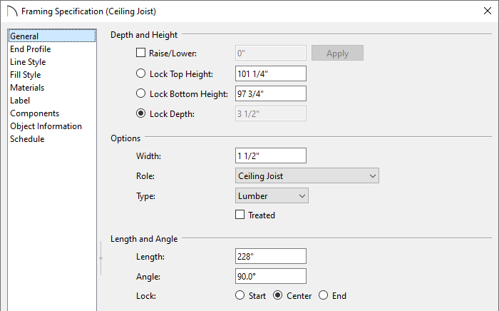
- Specify the desired Width, Role, and Type.
In this example, 1 1/2" thick Lumber is used.
- Specify the desired depth using the Lock Depth field, then click the radio button beside this field to lock this value.
In this example, 3 1/2" is used.
- Specify the desired top height using the Lock Top Height field. Use the value you determined in Step 3, above, which is 101 1/4" in this example.
- Press the Tab key on your keyboard to update the dialog, then confirm that your changes are all correct.
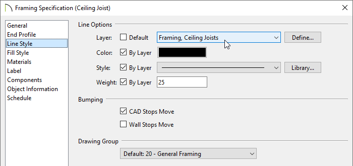
- On the Line Style panel, use the Layer drop-down to select the "Framing, Ceiling Joists" layer from the list, then click OK.
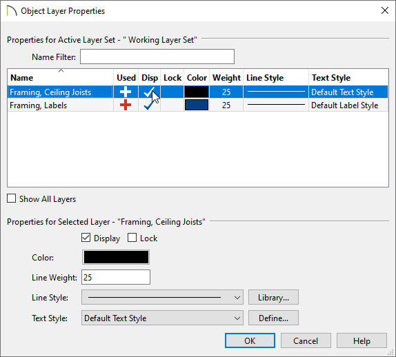
- With the framing member still selected, click the Object Layer Properties
 edit button to open the Object Layer Properties dialog, place a check in the Disp column or Display checkbox for the "Framing, Ceiling Joists" layer, then click OK.
- Move the framing member into position along the inside surface of a wall's Main Layer using whatever method you prefer. For example:
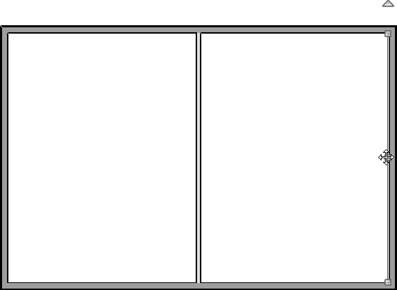
- Using its Move
 edit handle;
- Using a dimension line;
- Using the Transform/Replicate Object
 edit tool;
- Using the Point to Point Move
 edit tool.
- Once the framing member is positioned against a wall, select it and click the Multiple Copy
 edit button, then click-and-drag to produce copies at regular intervals.
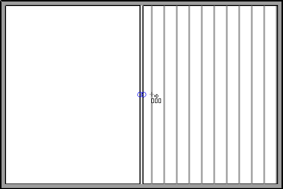
- You can add ledger boards for the lowered ceiling joists using the same steps:
- Draw a General Framing
 object;
- Edit its Depth, Top Height, and other attributes as needed;
- Move it into position.
- To trim the dropped ceiling joists so that they butt against the ledger instead of extending into it, use the Trim Objects
 edit tool:
-
Zoom
 in on the ledger so you can see it clearly.
- Click on the ledger to select it;
- Click the Trim Objects
 edit tool;
- Click and drag to draw a temporary fence inside of the ledger and through the joists that you wish to trim.
- When you release the mouse button, all joists touched by the temporary fence will trim to the edge of the ledger.
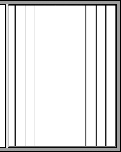
- You can now see the lowered ceiling framing in a Backclipped Cross Section
 if you turn on the display of the "Framing, Ceiling Joists" layer.

 tool to select the room that you want to assign a dropped ceiling to, then click the Open Object
  edit button.


 view.
view.
 edit button.
 from the menu, then click and drag to draw a framing member across the room with the lowered ceiling.
 edit button.

 edit button to open the Object Layer Properties dialog, place a check in the Disp column or Display checkbox for the "Framing, Ceiling Joists" layer, then click OK.

 edit tool;
 edit button, then click-and-drag to produce copies at regular intervals.
 object;
 edit tool:
 in on the ledger so you can see it clearly.
 edit tool;
 if you turn on the display of the "Framing, Ceiling Joists" layer.