QUESTION
I'm building an unfinished structure with exposed studs. How do I create these walls that will show the exposed wall framing?

ANSWER
To create a wall with exposed studs you must create a custom wall type with no interior wall layers, generate wall framing, and then turn on the display of the "Framing, Wall" and "Framing, Headers" layer(s) while in a camera view.
To create an exposed stud wall type
- In the plan where you want to create walls with exposed studs navigate to Build> Wall> Define Wall Types
 .
.
- In the Wall Type Definitions dialog that displays:
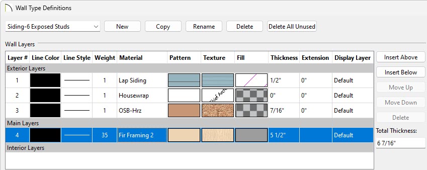
- Click on the Wall Type drop-down menu located in the top left corner to choose a wall type that contains a framing layer.
In this example, the Siding-6 wall type was selected.
- Select the Copy button to copy the wall type that was selected, then give it an appropriate name.
In this example, the name is set to "Siding-6 Exposed Studs".
- Select any Interior Layers that exist in this wall type, then click the Delete button on the right to remove them from the wall.
In this example a single Drywall Interior Layer was deleted.
In X15 and prior, the Interior Layer containing a line style cannot be removed.
- Make any other desired modifications to the wall type, such as changing the materials and thickness of the Exterior Layers, then click OK.
For more information on customizing and defining wall types, along with the various settings located in this dialog, please see the "Defining a New Wall Type" resource in the Related Articles section below.
- Using the Select Objects
 tool, click on the wall or walls that you want to use this wall type for, then click on the Open Object
  edit tool.
For more information on selecting multiple objects at once, please see the "Group Selecting Objects" resource in the Related Articles section below.
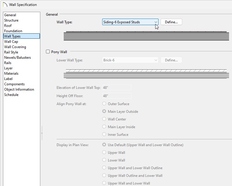
- In the Wall Specification dialog that appears, select the Wall Types panel, choose your custom wall type using the Wall Type drop-down menu, then click OK.
- Create an interior Camera
 view looking towards one of the walls utilizing the custom wall type.
- If wall framing is not set to automatically rebuild, navigate to Build> Framing> Build Framing
 while the camera view is active.
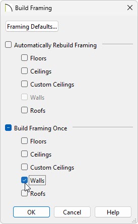
- In the Build Framing dialog, place a check in the Walls box in either the Automatically Rebuild Framing or Build Framing Once section.
In X15 and prior, on the Wall panel of the Build Framing dialog that displays, place a check in the Build Wall Framing box, then click OK.
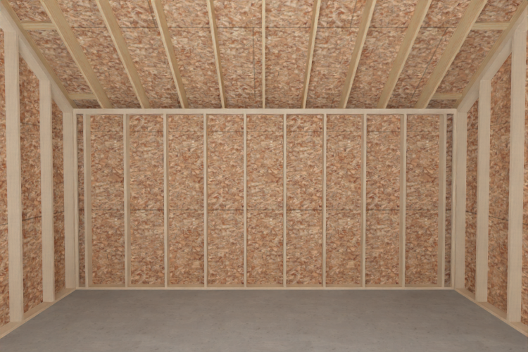
- Select 3D> Rebuild 3D
 to update the view and see the results.
If this wall type will be utilized in future projects, consider selecting a wall that is utilizing the custom wall type, then clicking the Add to Library edit tool. The wall will be added to the User Catalog folder within the Library Browser and can be selected and used to create new walls in your plans, similar to how the Wall tools work in the program.