QUESTION
I would like to create a structurally detailed pole building, or pole barn, using post-frame construction. How can I accomplish this?

ANSWER
A pole building, or pole barn, can easily be created in Chief Architect X13 and newer versions by using properly setup wall types, framing, and roof components.
In addition to this article, you can find a Post Frame Design sample plan and other related resources on our Samples Gallery page. Please be aware that due to varying post-frame construction design methods, you may notice differences between the sample plan, related resources, and the content located within this article.
There are a number of tasks involved in creating a structure using post-frame construction, including:
Before starting work on any drawing, it is important to set up the correct default settings, particularly for the structural aspects of the plan.
As you set up your defaults, you can also set up defaults for door styles and materials for roofing, casing, doors, and other items.
Setting up defaults
- Before setting up the Default Settings
 , we will create a wall type that will be specific to post-frame construction. To begin, select Build> Wall> Define Wall Types
  from the menu, then click the New button to create a new wall type.
To learn more about wall types, please see the "Defining a New Wall Type" resource in the Related Articles section below.
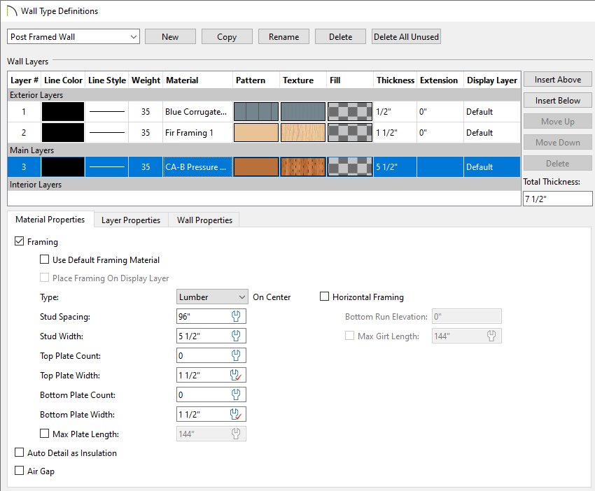
- Give the wall type a Name using the field in the top left corner.
In this example, the name of Post Framed Wall is specified.
- Use Insert Above or Insert Below to add the different wall layers - an exterior finish layer, an exterior framing layer for girts, and a main layer consisting of pressure treated framing for the posts.
In this example, the exterior finish layer is set to a corrugated metal material.
- For each layer of the wall type, set the Thickness.
In this example, the Thickness values are set to 1/2" for the exterior finish layer, 1 1/2" for the layer that will become our girts, and 5 1/2" for the posts layer.
- For the layer that will be used as girts, check the box for Framing, set the Stud Spacing and Stud Width, check the box for Horizontal Framing, and specify the Bottom Run Elevation to your liking.
In this example, the Stud Spacing is set to 24", the Stud Width is set to 5 1/2", and the Bottom Run Elevation is set to 0".
- For the layer that will be used for posts, check the box for Framing, set the Stud Spacing and Stud Width, Plate Counts, and make any other desired adjustments.
In this example, the Stud Spacing is set to 96", the Stud Width is set to 5 1/2", and the Top and Bottom Plate Counts are set to 0.
- Make any other adjustments to the wall type, as desired.
- Next, select Edit> Default Settings from the menu to open the Default Settings dialog.
- To expand a category in the tree list and view its subcategories, click the arrow to the left of its name.
- To open the defaults dialog for a line item, click on its name and then click the Edit button, or simply double-click on its name.
- In the Exterior Door Defaults dialog:
- On the General panel, specify the Door Style of the exterior man door that you would like, as well as the Width and Height.
In this example, the Door P09 from the library is used, and the default values are used for the Width and Height.
- On the Casing panel, specify whether or not to use casing, and if so, adjust the properties accordingly.
- On the Sill/Threshold panel, specify whether or not to use a threshold.
In X15 and prior, sill/threshold settings for doors are located on the Casing panel.
- On the Jamb panel, set the jamb properties to your liking.
If wall girts will be covering the door jamb, consider unchecking the Fit Jamb to Wall box and changing the Depth and/or Inset values.
- On the Rough Opening panel, set the rough opening properties to your liking.
In X13, the Rough Opening information is located on the Framing panel.
In this example, we will account for the 3/4" default Jamb value located around the door, so we will specify the Additional Width to be 1 1/2" (3/4" x 2) and the Additional Height to be 3/4". In X14 and prior, specify 3/4" for Each Side, 3/4" for the Top, and 0" for the Bottom instead.
- On the Framing panel, specify the desired header information, such as Thickness, Count, and Framing Method*, as well as the Trimmer and King Stud Count**.
In this example, we have specified a Flat Header* with a Count of 1, a Trimmer Count of 1, and a King Stud Count of 1. Manual modification of these framing members may be required after framing has been generated. This is discussed more in the Making manual framing adjustments section.
*The Framing Method drop-down menu allows you to choose between Standard, Boxed, and Flat headers, and is only available in X16 and newer versions. In X15 and prior, specify a Standard header with a Count of 1, then swap the Thickness and Depth values to simulate a flat header, if desired. Calculate from Width must be unchecked to change the Depth.
**Available in X14 and newer versions. In X13, king studs were generated automatically. Set the Trimmer Count to 1 to generate the same number of studs for the doors.
- Access any other panels that you would like to make changes to before closing out of the dialog.
- In the Garage Door Defaults dialog:
- On the General panel, specify the Door Style of the garage door that you would like, as well as the Width and Height.
In this example, the Garage Door P02 from the library is used, and a value of 120" (10') is specified for both the Width and Height.
Additional garage door options are available in the Amarr® and Clopay® manufacturer catalogs. Please see the "Obtaining and Updating Library Content" resource in the Related Articles section below to learn more.
- On the Casing panel, specify whether or not to use casing, and if so, adjust the properties accordingly.
- On the Sill/Threshold panel, specify whether or not to use a threshold.
In X15 and prior, sill/threshold settings for doors are located on the Casing panel.
- On the Jamb panel, set the jamb properties to your liking.
If wall girts will be covering the door jambs, consider unchecking the Fit Jamb to Wall box and changing the Depth and/or Inset values.
- On the Rough Opening panel, set the rough opening properties to your liking.
In X13, the Rough Opening information is located on the Framing panel.
In this example, we will account for the 3/4" default Jamb value located around the door, so we will specify the Additional Width to be 1 1/2" (3/4" x 2), and the Additional Height to be 3/4". In X14 and prior, specify 3/4" for Each Side and 3/4" for the Top, and 0" for the Bottom instead.
- On the Framing panel, specify the desired header information, such as Thickness, Count, and Framing Method*, as well as the Trimmer and King Stud Count**.
In this example, we have specified a Standard Header with a Count of 2, a Trimmer Count of 1, and a King Stud Count of 1. Manual modification of these framing members may be required after framing has been generated. This is discussed more in the Making manual framing adjustments section.
*The Framing Method drop-down menu allows you to choose between Standard, Boxed, and Flat headers, and is only available in X16 and newer versions.
**Available in X14 and newer versions. In X13, king studs were generated automatically. Set the Trimmer Count to 1 to generate the same number of studs for the doors.
- Access any other panels that you would like to make changes to before closing out of the dialog.
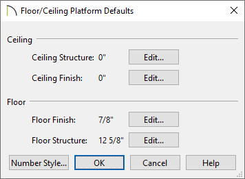
- In the Floor/Ceiling Platform Defaults, which is located under the Floors and Rooms category, modify or delete layers from the Ceiling Structure, Ceiling Finish, Floor Finish, and Floor Structure.
In this example, all layers from the Ceiling Structure and Ceiling Finish sections have been deleted, resulting in a 0" Thickness. The Floor Finish and Floor Structure are unchanged, as we will cover this topic within the Creating the initial structure and placing openings section below.
- In the Framing Defaults dialog:
- On the Wall panel, set the Plate Counts if this was not changed, or available, when defining the wall type.
In this example, the Top and Bottom Plate Count are both set to 0.
- On the Openings panel, ensure the Header Sizes for the different spans are set properly.
- On the Trusses panel, under the Roof Trusses section, set the correct Member Depth for the Top Chord, Bottom Chord, and Webbing, the Maximum Horizontal Span for the Top and Bottom Chord, and whether or not the Require Kingpost and Energy Heel* boxes are checked.
In this example, the Top and Bottom Chords are set to 5 1/2" and the Energy Heel box is checked. All other settings are unchanged.
*Available in Chief Architect X14 and newer versions. In X13 and prior versions, trusses can only be marked as such within the Truss Specification dialog. Please see the Related Articles section for more information on creating energy heel trusses.
- Edit any other settings that you desire, apart from those located on the Roof panel. We will discuss roof defaults, including roof framing, in the next step.
- In the Roof Defaults dialog:
- On the Roof panel, set the Framing Method to Trusses.
In X14 and prior, check the Trusses (no Birdsmouth) box instead.
- Specify the desired roof Pitch (in 12).
In this example, a Pitch of 4 in 12 is specified.
- Set the Roof Height properties, such as the Heel Height.
In this example, the Heel Height is set to 6 1/4". This value will vary depending on the pitch that you specify.
In X14 and prior, a Heel Height option is not available. Instead, uncheck the Automatic Birdsmouth Cut box, then specify a Raise Off Plate (+) or Birdsmouth (-) value to create an energy heel. Specify a value of 7/16" to produce a 6 1/4" Heel Height.
- Set the Roof Overhang on the Eave and Gable to the values you desire.
In this example, a value of 12" is specified for each.
- On the Options panel, specify your desired Eave settings.
In this example, the default Plumb option is selected.
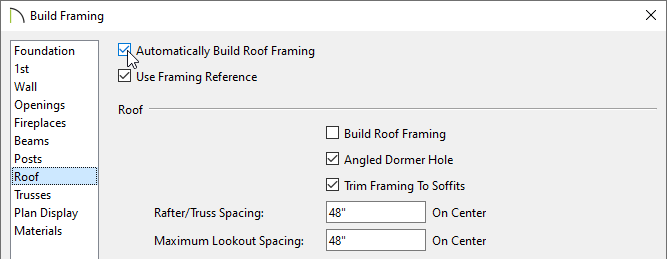
- On the Structure panel, check the Use Framing Reference box and change the Rafter/Truss Spacing to your preference.
In this example, a value of 48" is specified.
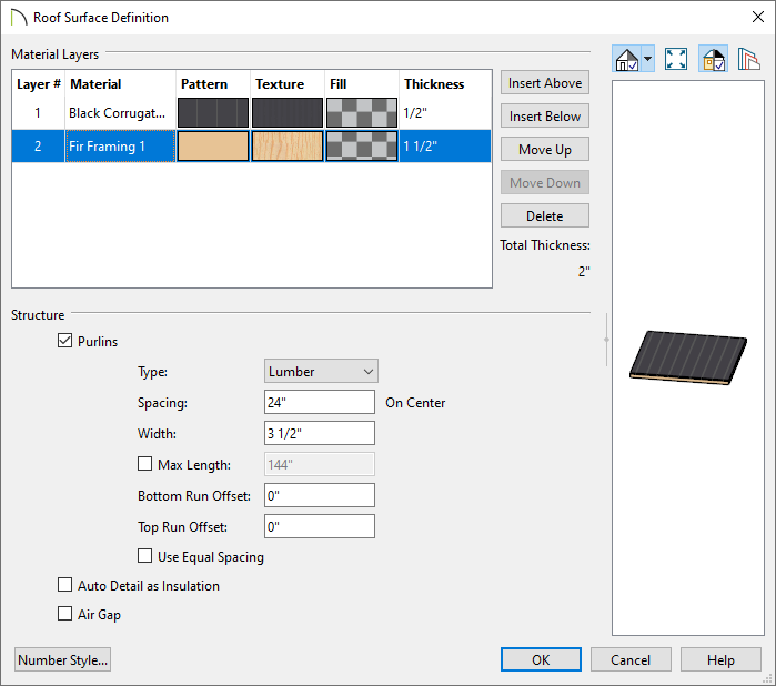
- Under the Roof Layers section, Edit the Roof Surface and define a roof purlins framing layer along with a roof exterior surface layer, then click OK.
In this example, a purlins layer with a Thickness of 1 1/2", a Width of 3 1/2", and a Spacing value of 24" is specified. Another layer consisting of corrugated metal with a Thickness of 1/2" is defined for the exterior roofing material.
- To create exposed trusses on the exterior of the structure, uncheck the Soffits box.
In this example, the Soffits box is checked.
- Under the Roof Size section, adjust the properties of other elements of the roof, as desired.
In this example, we have unchecked the Lookout box and adjusted the Ridge board to have a Depth of 5 1/2" to match our trusses. This will create blocking between our trusses at the ridge.
- Make any other desired changes, such as to the Ridge Caps, Gutters, Materials, etc.
- On the Wall Types panel of the Exterior Wall Defaults dialog, use the Wall Type drop-down to select the "Post Framed Wall" wall type created earlier.
- Windows are not used in this example, but if you will be adding windows to your design, access the Windows Defaults dialog:
- On the General panel, specify the Window Type, as well as the Width, Height, and Floor to Top/Bottom values.
- Access the Casing, Sill/Threshold, Sash, and Frame panels to adjust these window settings, as necessary.
In X15 and prior, access the Sill panel to adjust sill settings for windows.
- Set the rough opening and frame properties by accessing the Rough Opening and Frame panels.
In X13, the Rough Opening information is located on the Framing panel.
- Access the Framing panel, specify the desired header information, such as Thickness, Count, and Framing Method*, as well as the Trimmer and King Stud Count**.
As with doors, manual modification of these framing members may be required after framing has been generated. This is discussed more in the Making manual framing adjustments section.
*The Framing Method drop-down menu allows you to choose between Standard, Boxed, and Flat headers, and is only available in X16 and newer versions.
**Available in X14 and newer versions. In X13, king studs were generated automatically.
- Access any other panels that you would like to make changes to before closing out of the dialog.
If you plan to design these types of structures in the future, now is a great time to save your default settings for use as a template plan. To create a template plan, select File> Templates> Save As Template  . Give the file a short, descriptive name, and save it in the Chief Architect Templates directory, or the location of your choice.
The program may ask if you want to make your new template your default template for new plans. Unless you expect that most of your new projects will use post-frame construction, click No. Once the defaults are set up, the structure can be drawn.
Creating the initial structure and placing openings
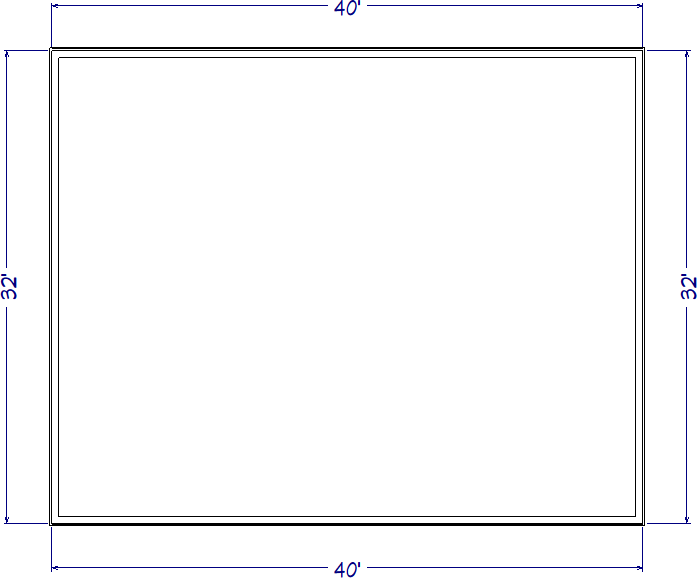
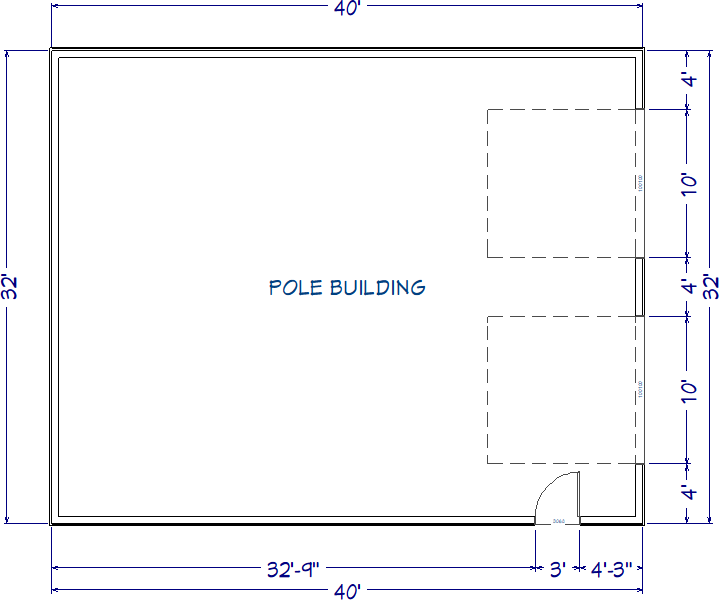
- With the Build> Walls> Straight Exterior Wall
 tool, draw the perimeter walls for your pole building.
In this example, we drew a 32' x 40' rectangular structure.
- Using the Select Objects
 tool, click inside of the newly created room, then click the Open Object
  edit tool.
- In the Room Specification dialog that displays:
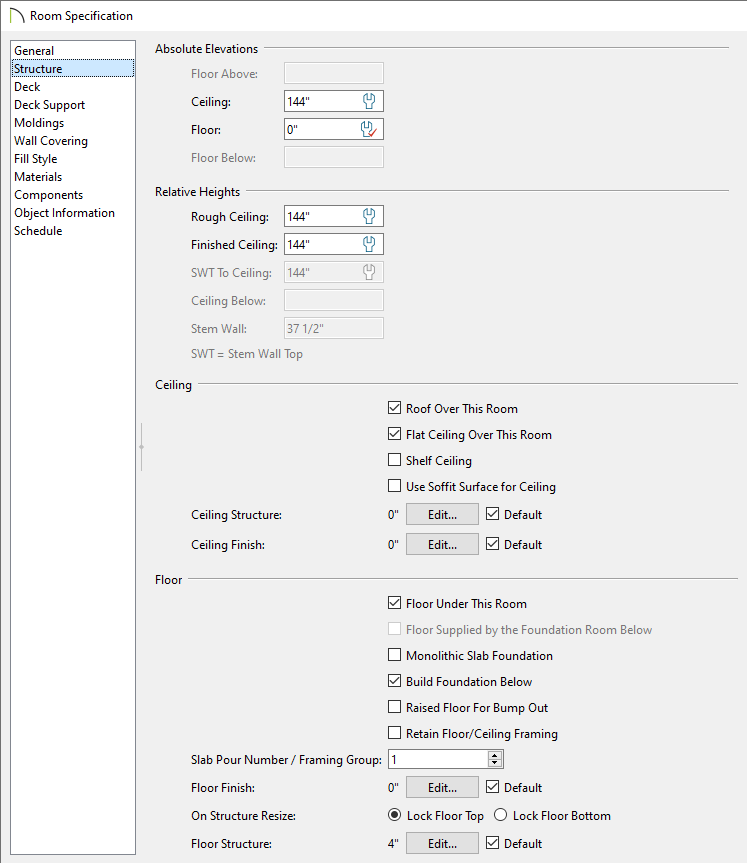
- On the General panel, specify the Room Type to be a Slab if you would like a 4" concrete slab as your floor platform, then specify an appropriate Room Name such as "Pole Building".
- On the Structure panel, specify the desired Ceiling height, which determines the top of the wall, as well as the elevation at which the roof trusses' bottom chords will start.
In this example, 144" (12') is used.
- Also on the Structure panel, ensure that the Ceiling and Floor sections are following what was set within the Floor/Ceiling Platform Defaults, or are set to your liking.
- Make any other desired changes, then click OK.
- Using the different Door
 and Window
  tools, add any openings that are needed for the structure.
In this example, we have added a standard man door measuring 36" (3') wide and 80" high, and two garage doors that measure 120" (10') wide and 120" (10') high.
Building the roof
- Using the Select Objects tool, click on one of the end walls, click on the Open Object edit tool, and on the Roof panel of the Wall Specification dialog that displays:
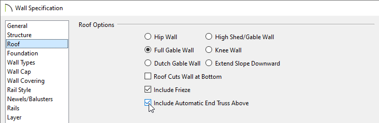
- Select the Full Gable Wall option.
- In X15 and newer, check the Include Automatic End Truss Above if you would like a reduced gable end truss to be generated above this wall when trusses are automatically generated.
In X14 and prior, trusses will need to be created manually, which is discussed in the Creating roof trusses manually section below.
- Click OK to confirm the changes and close the dialog.
-
Repeat the above process on the opposite end wall.
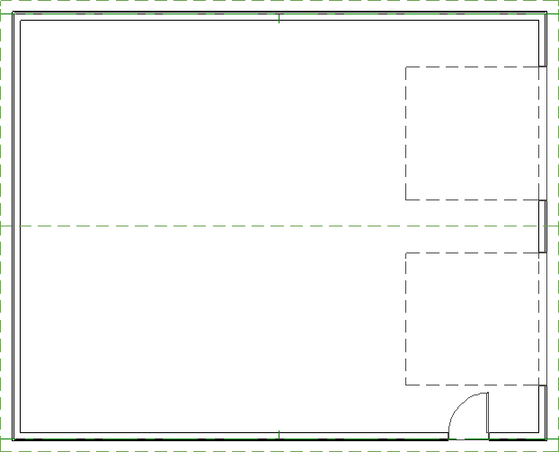
- If Auto Rebuild Roofs is not currently enabled, navigate to Build> Roof> Build Roof
 , check the Auto Rebuild Roofs box located on the Roof panel, then click OK to generate the roof.
Framing walls
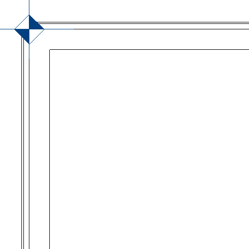
- Navigate to Build> Framing> Framing Reference Marker
 and place a framing reference marker at the corner where two walls meet, making sure it's placed along the main layer that contains the posts. This will dictate where the wall framing starts at.
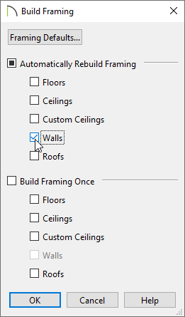
- Next, navigate to Build> Framing> Build Framing
 .
.
- In the Build Framing dialog, check the Walls box under either the Automatically Rebuild Framing or Build Framing Once section.
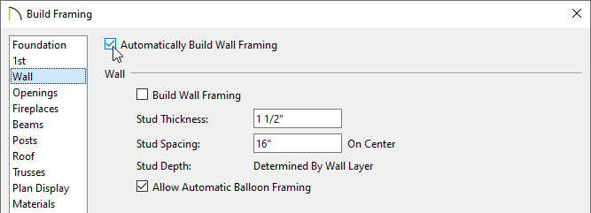
In X15 and prior, check the Automatically Build Wall Framing or Build Wall Framing box located on the Wall panel.
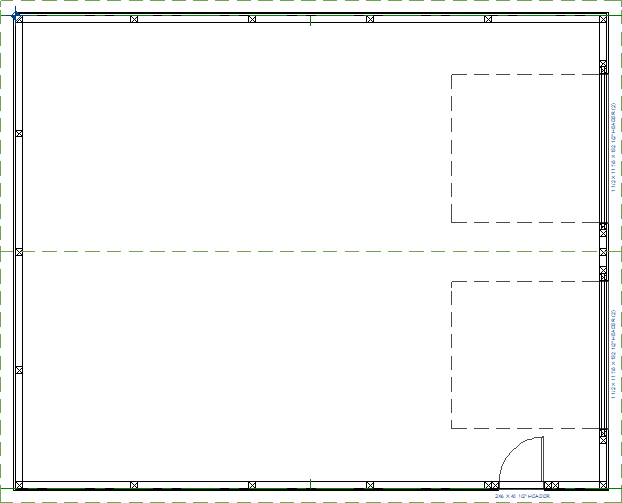
- Click OK to close the dialog and generate wall framing, which will include headers, posts, and girts.
Creating roof trusses automatically*
*Applies to Chief Architect Premier X15 and newer versions.
- Select Build> Framing> Build Framing from the menu.
- In the Build Framing dialog that appears, check the Roofs box under either the Automatically Rebuild Framing or Build Framing Once section.
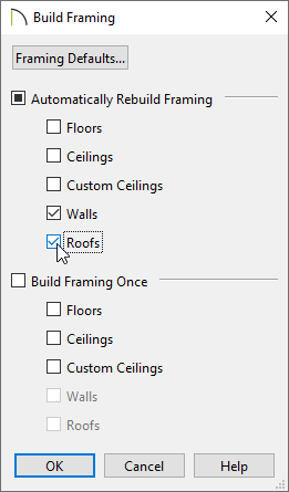
In X15, check the Automatically Build Roof Framing or Build Roof Framing box located on the Roof panel.
- Click OK to generate automatic trusses, purlins, as well as additional roof framing components.
- To adjust the properties of an individual roof truss further, click on it to select it, then click the Open Object edit tool to access the Roof Truss Specification dialog.
Creating roof trusses manually
If you're using X14 or a prior version, trusses will need to be created manually. Please follow the instructions below to learn how to place and replicate roof trusses.
- Select Build> Framing> Roof Truss
 from the menu, then click and drag to draw a roof truss near one of the main posts towards the outside of the structure.
- Click on the newly placed roof truss to select it, then use a Temporary Dimension or the Move
 edit handle to position it precisely.
- Keep placing roof trusses until you reach the other side of the pole building. You can also use the Transform/Replicate Object
 or Multiple Copy
  edit tools to quickly replicate trusses across a plan.
- Select the outermost truss on the left-hand side of the building and click the Open Object edit tool.
- On the General panel of the Roof Truss Specification dialog, check the End Truss and Reduced Gable boxes if they aren't already checked, then click OK. Repeat this process for the truss on the opposite end of the building.
Generating roof purlins
If you generated automatic trusses in X15 or a newer version, it's likely that purlins have already been generated. You can skip to the next section if purlins have already been built.
- Navigate to Build> Framing> Build Framing from the menu.
- In the Build Framing dialog that appears, check the Roofs box under either the Automatically Rebuild Framing or Build Framing Once section.
In X15 and prior, check the Automatically Build Roof Framing or Build Roof Framing box located on the Roof panel.
- Click OK to generate automatic purlins, as well as additional roof framing components.
Making manual framing adjustments
If additional framing needs to be added (e.g. wind bracing), adjusted, or removed, manual modifications may be in order.
It's important to be aware that making manual framing adjustments may require you to disable automatic rebuild functionality for one or more framing categories. With this in mind, it's recommended to only make manual adjustments after you are finished using the automatic framing capabilities.
If framing needs to be rebuilt, manual adjustments will be overridden unless the Retain Framing setting is specified for the object. This setting prevents new framing from generating, and can be found on the Structure panel of Wall, Ceiling, Room, and Roof Plane Specification dialogs.
You can rebuild framing on a per object basis using the Build Framing for Selected Object edit tool while a valid object (e.g. wall, roof, etc.) is selected. This edit tool; however, will not appear for objects that have Retain Framing selected.
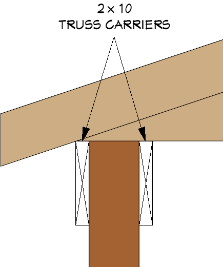
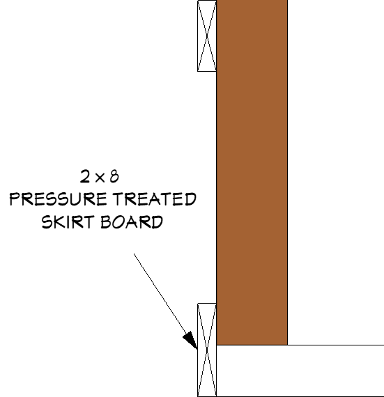
In our current design, a few manual adjustments that we still need to make include adding truss carriers for the roof trusses, modifying the bottom skirt (girt) boards to be treated and flush with the concrete piers, adjusting the trimmers, headers, king studs, and girts around the doors, and extending/shortening posts. Cross Section/Elevation  and/or Backclipped Cross Section
  views are recommended for making these type of framing adjustments. To make it easy to see our framing in these views, we will use the 3D Framing Layer Set.
Start by deleting any framing objects that are not needed.
For the truss carriers, we will copy an existing girt, place it into position, then adjust them to be 2x10s. Repeat for the opposite side of the structure.
For the skirt boards, we will select and lower their position, adjust them to be 2x8s, then apply a pressure treated framing material. Perform this procedure for each of the skirt boards around the structure.
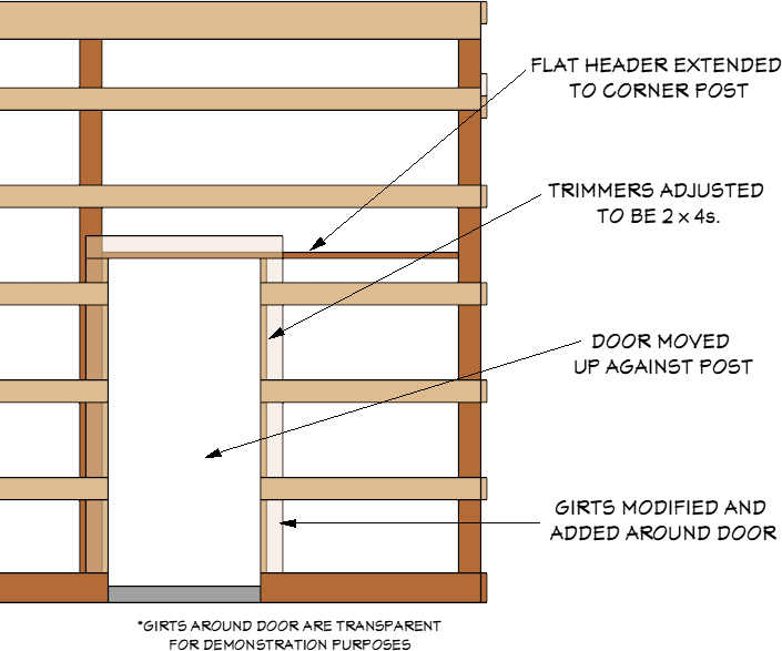
For the man door, we will adjust the flat header to extend to meet the corner post, adjust the trimmers to be 2x4's, and move the door and trimmers up against the post. Finally, we will adjust and place additional boards around the door.
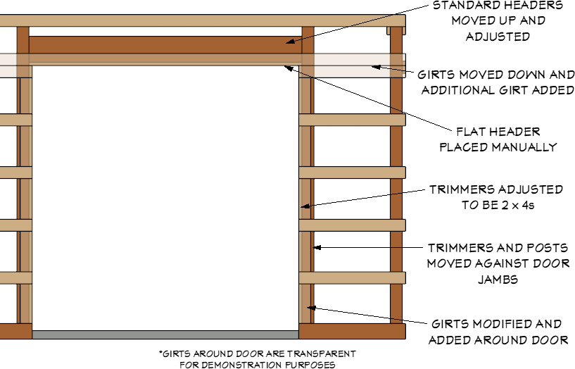
For the garage doors, we will modify the trimmers to be 2x4s, then move the trimmers and king studs up against the door jambs. We will raise the standard headers up 1 1/2", adjust them accordingly, then place a general framing member to act as a flat header. Next, we will move the existing girts at the top of the garage doors down to accommodate additional girts. Finally, we will adjust and place additional boards around the doors.
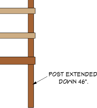
With all of the framing now positioned, we can extend/shorten the posts using edit handles in a section view or by accessing the Specification dialog. For our design, we will extend our posts down 46" to increase their total width to 190", as they will be contained within piers (discussed in the next section).
You can learn more about making manual framing adjustments in the following resources:
Generating piers
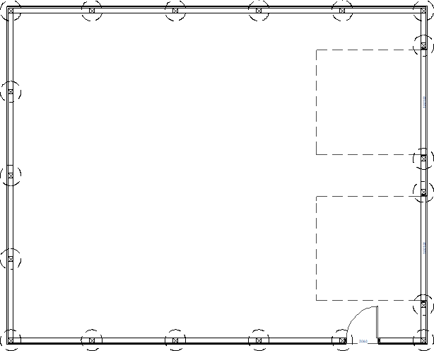
- In a floor plan view, navigate to Build> Slab> Round Pier
 and place a pier directly below one of your posts, preferably not a corner post.
- Using the Select Objects tool, click on the pier to select it, and Open it specification.
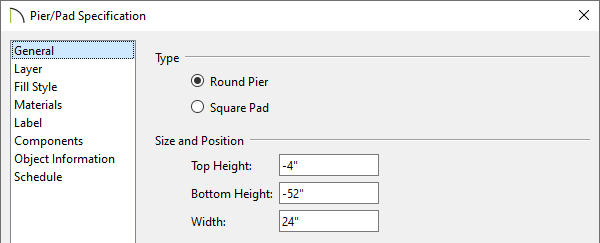
- In the Pier/Pad Specification dialog that opens, specify your desired properties of the pier, then click OK.
In this example, a Top Height of -4", a Bottom Height of -52", and a Width of 24" are specified.
- With the pier still selected, click on the Copy/Paste
 edit tool, click on the Sticky Mode
  secondary edit tool, then go around the structure clicking at the Center
  snap point of each post until all of the piers are placed.
You can also use a variety of other edit tools to easily copy/paste piers precisely beneath your posts, such as Multiple Copy, Transform/Replicate Object, and Point to Point Move.
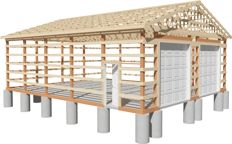
- Create a Camera
 view, such as a Perspective Framing Overview
  view to see the results. Switch to your desired Layer Set or toggle the display of layers using the Display Options
  or Active Layer Display Options
  side window.
MORE INFORMATION
- 3D views of the structure can be produced using any of the 3D Camera tools. However, by default, most of the framing layers are turned off aside from Framing Overviews. If you would like posts, girts, purlins, and other items to display in a particular type of 3D view, create the view, then either switch the Layer Set being used or toggle the display of layers, as desired. Please refer to the Understanding Layers, Understanding Layer Sets, and Understanding Saved Plan Views resources to learn more. You can find additional information in the Cameras & Lighting and Saved Plan Views, Layers, & Annotations video playlists.
- Consider using the Object Eyedropper
 tool to quickly, and easily, apply properties from one object to another. Please refer to the Using the Object Eyedropper and Painter video to learn more.
- You can add finishing touches, such as truss connectors, fasteners, straps, and ties using the objects located in the Simpson Strong Tie® manufacturer catalog.
- Corner boards can be added to the structure by navigating to Build> Trim> Corner Boards
 or Auto Place Corner Boards
  . Defaults for corner boards can also be specified before they are created.